MAINTENANCE
MAINTENANCE
68 • On-Demand Water Heater Service Handbook for 240, 340 & 540 Condensing Models
16.2
Slide the black igniter
wire onto the igniter rod.
See “Igniter Rod Wire
Connecon” in Figure 41,
page 49.
17. Install the flow sensor/control valve
(item 402, p. 74) and cold pipe (item
466, p. 74) as follows:
17.1
Install the ow sensor/
control valve onto the water
inlet connecon (boom,
center of cabinet).
the solenoid valve with
the matching number
except as noted below.
•
The proporonal valve
does not have a number
and is located at the
boom of the assembly.
Connect the wire
assembly with red and
white wires to its fork
terminals.
13.2
Make sure that the screen
inside the gas valve inlet is
sll in place.
13.3
Slide the gas valve/manifold
plate assembly onto the
gas inlet connecon. (The
gas inlet is located at the
boom, right-hand corner of
cabinet.)
You may need to rotate
the gas valve while sliding
it down for an easier t.
The tab on the gas valve
connecon should line up
behind the tab on the gas
inlet connecon.
13.4
Secure the gas valve to the
gas inlet by installing the
brass screw (with washer)
through both tabs at the
connecon. Hand-tighten
only.
See “Brass Screw Securing
Gas Valve...” in Figure 41, p.
49.
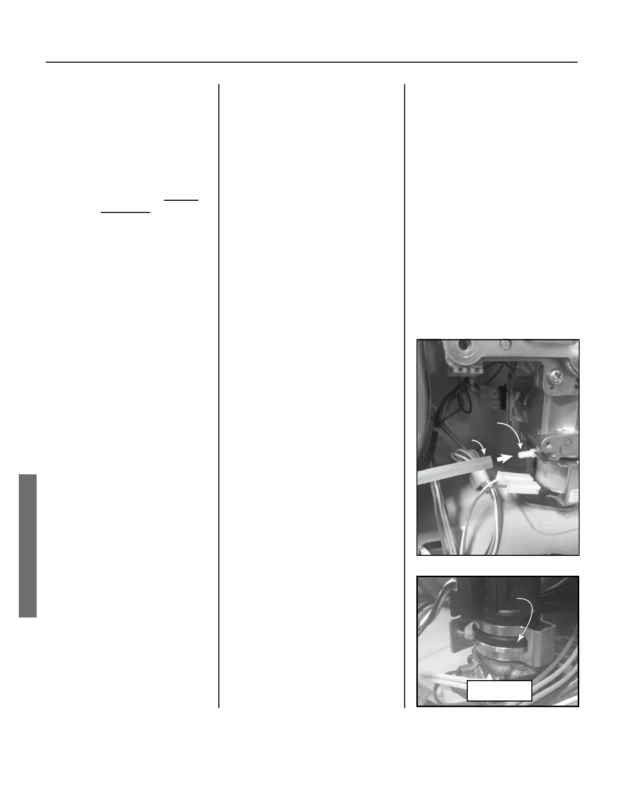
13.5
Aach the air tube from the
boom of the combuson
chamber to the port on the
le side of the gas valve.
(See Figure 69.)
NOTICE: If the air tube is not
connected to the boom of
the combuson chamber,
connect it now as shown in
Figure 58 (p. 63).
14. INDOOR MODELS ONLY:
Secure the power cord to the
manifold plate as shown in Figure
Hand-tighten only.
Use the mounting tab and its
M4X10 screw.
15. Secure the manifold plate:
15.1 Line up the manifold plate
with the holes on the burner,
then hand ghten the top
center screw on the manifold
plate. (See “Manifold Plate,”
page 49.)
15.2
Hand ghten the remaining
manifold plate screws.
NOTICE: Leave the following
mounng holes open:
◦ Fuse box mounting holes
(left side of plate)
◦ Igniter assembly mounting
hole (top, right-hand side
of plate)
◦ Ground wire mounting
location (bottom, center
of plate).
16. Install the igniter assembly to
the top, right-hand corner of
the manifold plate. (See “Igniter
Assembly” and “Igniter Rod Wire
16.1 Insert and hand ghten the
screw.
Air Tube Connection
Gas Valve
Port
Air Tube
Figure
Flange ts between top and
bottom of clip.
Figure 70.
16A Fastener
 Loading...


