MAINTENANCE
MAINTENANCE
On-Demand Water Heater Service Handbook for 240, 340 & 540 Condensing Models • 63
9.11
Inspect the o-ring (item 151,
p. 73) and gas inlet ring
(item 119, p. 73) at the
gas inlet for cuts or breaks.
If damaged, replace with
part number 100074242
(item 151) and/or
100074526 (item 119).
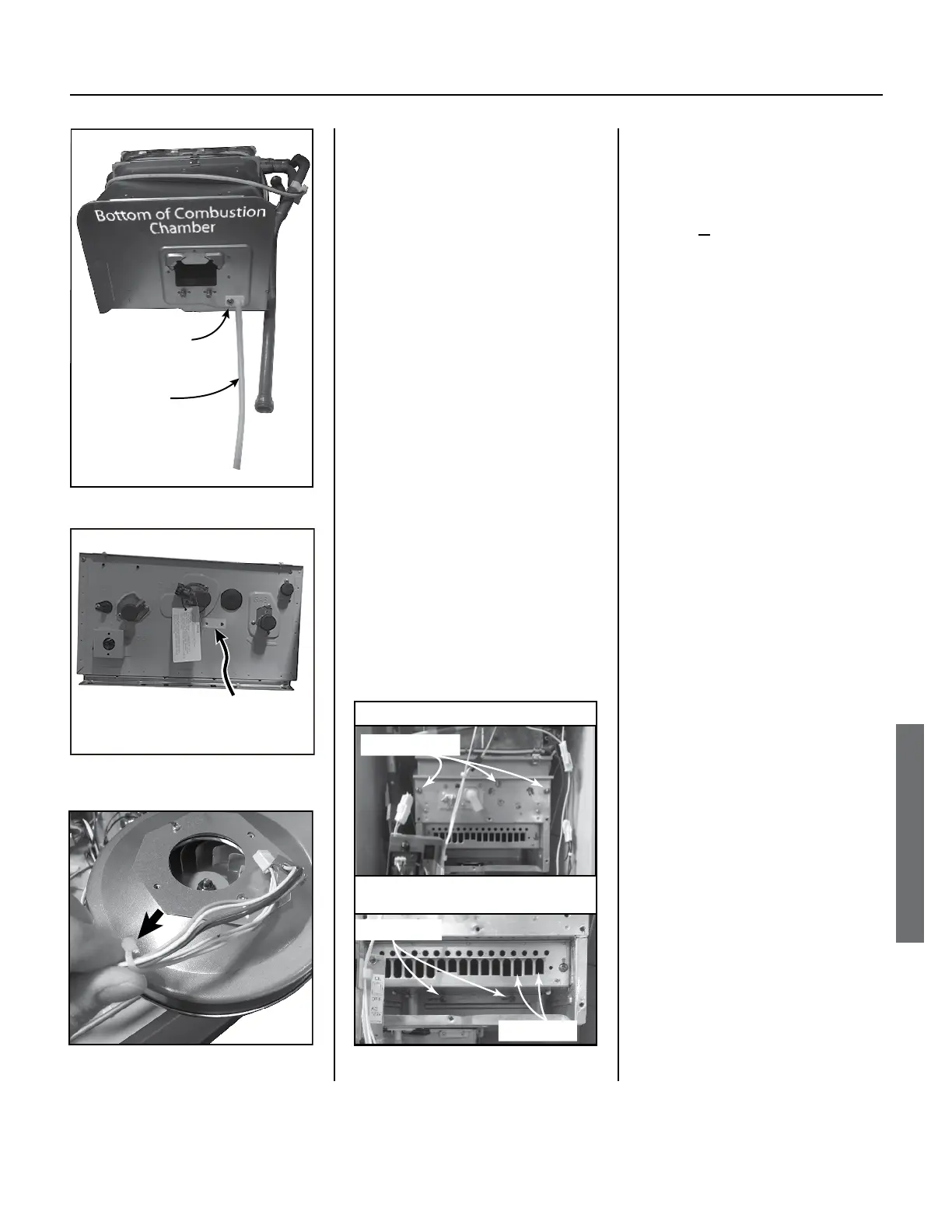
10. Disconnect and remove the fan from
10.1 Remove the clear air tube
from the boom of the
combuson chamber (Figure
58).
10.1 Remove the 2 Phillips/hex
head screws poinng down
from the fan using an 8”
long, #2 Phillips head screw
driver.
There are 2 holes in the case
directly below the screws to
put the screw driver through
(Figure 59).
Figure 58.
Figure 60.
10.2
Slide the fan toward you to
remove it from the rear slots
that hold it in place. Remove
the fan.
10.3
IF the fan wires are zip-
ed to the white Exhaust
Thermistor/High Limit Switch
wires, clip the zip e to
separate them (Figure 60).
NOTICE: Do not cut, nick,
or damage the wires when
clipping the zip e.
11. Remove the burner from the
11.1
Remove two screws below the
burner, at the back (Figure 61).
11.2
Remove three screws across
the front of the burner. See
Figure 61. Do not remove
the screws around the ame
sensor/AFR and igniter rods.
11.3
Remove the burner as
follows:
◦ Using pliers, grip the
burner on one side and
pull. (Grip at an inlet
hole; see
Figure 61.)
◦ Repeat on the opposite
side.
◦ Continue to pull on each
side in an alternating
fashion until the burner
begins to loosen. When
the burner loosens, pull
from the middle portion
until the burner slides
out toward you.
11.4
Check the gaskets on the
burner for any tears. If there
are, replace the gasket with
part number 100074217.
Front View of Burner Assembly
Three ScrewsThree Screws
Two Screws
Area Beneath Burner (Inside Cavity)
Inlet Holes
Figure 61.
Holes (2) for access to fan
screws. Both holes are
located under the tape.
Figure
 Loading...


