MAINTENANCE
MAINTENANCE
64 • On-Demand Water Heater Service Handbook for 240, 340 & 540 Condensing Models
Figure 63.
Three Screws Securing the
Secondary Heat Exchanger
12. Disconnect and remove the
following items:
12.1
Disconnect the condensate
drain line (item 416, page
74) from the secondary
heat exchanger assembly
by pulling down. Do not
remove the drain line from
the outlet connecon at the
boom of the cabinet.
12.2
Remove fastener 16-25
(item 462, page 74) from
the outlet tubing and outlet
water connecon.
12.3
Slide the outlet tube up and out
of the outlet water connecon.
12.4
Remove the drain pipe as
follows:
12.4.1
Remove the clips at the top
and boom of the drain
pipe. See page 74, items
465 and 463. (There are
two instances of item 463.)
12.4.2
Remove the drain pipe.
12.5
IF you have a 540 model,
remove the heat exchanger
thermistor as described
below:
12.5.1
Remove the clip that
secures the thermistor. See
Figure 62; see also “Heat
Exchanger Thermistor” in
Figure 41, p. 49.
12.5.2
Pull the thermistor out of
the copper pipe.
12.6
INDOOR MODELS:
Disconnect the venng from
the exhaust ue.
12.7
IF you have a 540 model,
disconnect the bypass valve
wiring as follows:
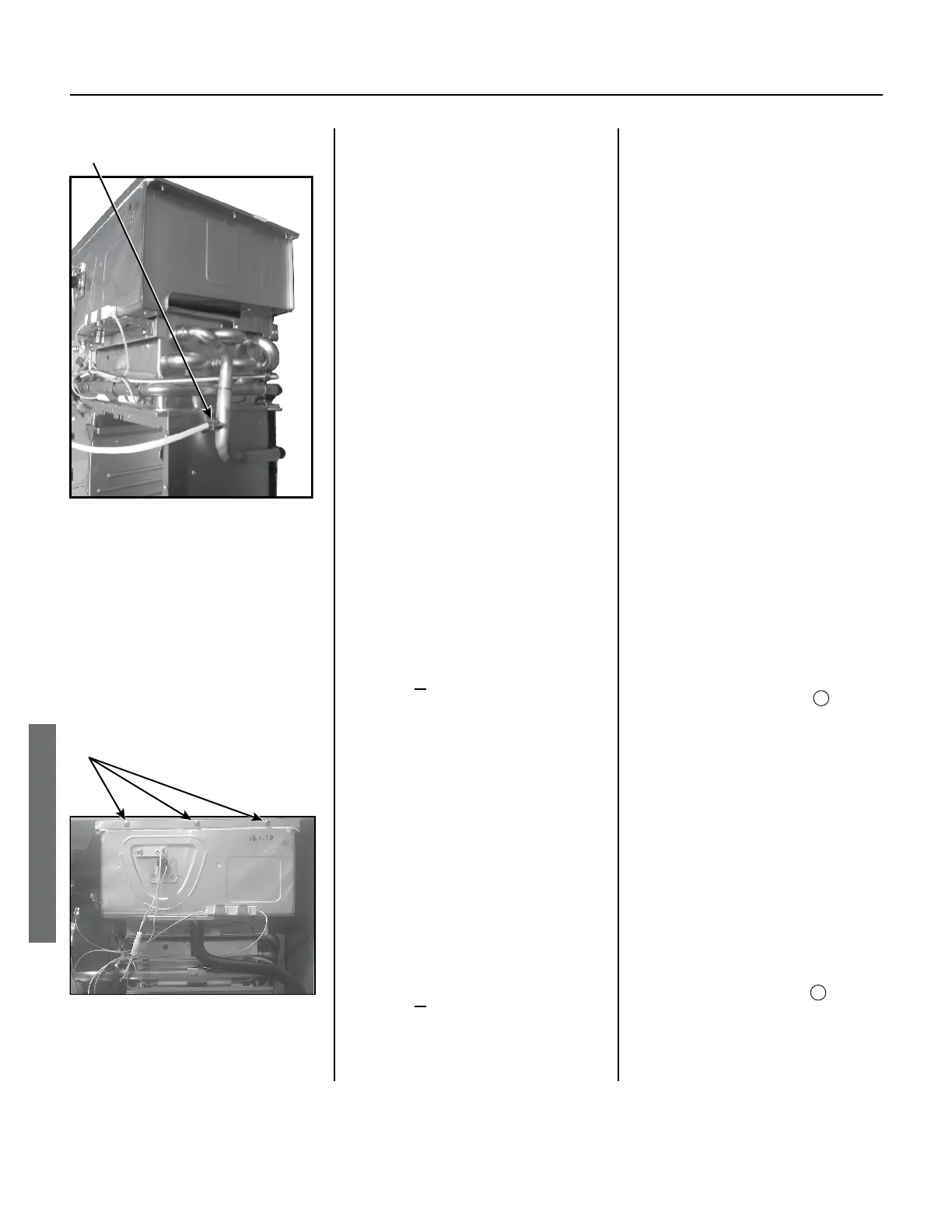
Heat Exchanger Thermistor
(540 Models Only)
View: Right Side of
Figure 62.
12.7.1
Locate the bypass valve
wires on the le side of the
heat exchangers.
Wire colors:
Red, Yellow, White, Blue,
Brown.
12.7.2
Disconnect the white
connector in the middle of
that wire run.
12.8
Remove the three screws
at the top of the secondary
heat exchanger that are
securing it to the case. Refer
to Figure 63. Save for future
use.
13. Follow these steps to remove the
heat exchangers:
13.1
Slide the heat exchangers
down while gradually angling
the boom toward you.
13.2
Separate the primary and
secondary heat exchangers
as follows:
13.2.1
Remove fastener 16-25
(connecon point
; item
462, page 74; ).
Locaon: Copper tube at top
of le-hand side. (This tube
connects the primary heat
exchanger to the secondary
heat exchanger.)
13.2.2
Remove two (2) ceramic
heaters that are clipped onto
the copper pipes on the
le-hand side of the cabinet.
(One heater is on the heat
exchanger out pipe, item
467. The other is just above
connecon point
. See
page 74.
 Loading...


