MAINTENANCE
MAINTENANCE
On-Demand Water Heater Service Handbook for 240, 340 & 540 Condensing Models • 53
•
NOTICE: DO NOT remove
the screws along the
interior of the manifold
plate.
5.3
INDOOR MODELS: Remove
the power cord mounng
tab. (Figure 41, page 49.)
5.4
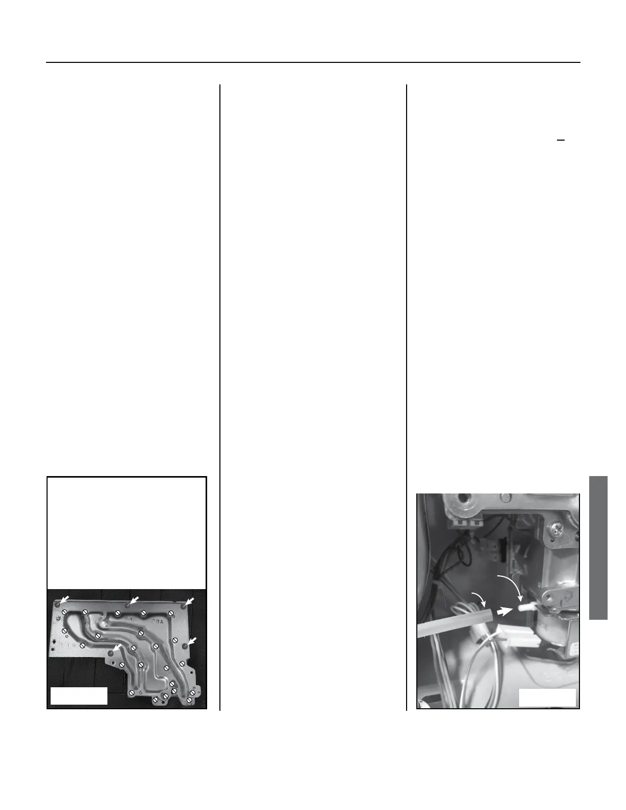
Disconnect the clear air tube
o the le side of the gas
valve. (Figure 44.)
5.5
Remove the screw securing
the gas valve to the gas inlet
connecon.
•
The screw is located at
the bottom, right-hand
side of the gas valve. See
OR
Figure 42 (p. 50).
•
If necessary, disconnect
the condensate tube
from the bottom, right-
hand side of the cabinet
first.
5.6
Li the manifold plate/
gas valve assembly upward
to remove it from the gas
inlet connecon. (The gas
valve and manifold are sll
connected together.)
You may need to twist the
gas valve/manifold assembly
slightly.
5.7
If necessary, unplug the
wire connectors from the
solenoid valves, main gas
valve, and proporonal
gas valve. (These valves
are connected to the back
corner of the manifold
plate.) There are ve
connectors that can be
unplugged from the
manifold plate assembly.
5.8
Inspect the gaskets on
the manifold plate for any
tears. If compromised,
replace with part number
100074229 (item 113) and/
or 100074230 (item 114).
See p. 73.
5.9
Inspect the o-ring (item 151,
p. 73) and gas inlet ring
(item 119, p. 73) at the
gas connecon for cuts or
breaks.
If damaged, replace with
part number 100074242
(item 151) and/or
100074526 (item 119).
6. Remove the burner assembly
according to the following steps.
6.1 Remove the ve (5) pan-
head Phillips screws that
secure the burner to the
combuson chamber. There
are three at the top of the
burner and two more at
the boom (toward back of
combuson chamber). If
the screws at the boom
are dicult to remove, li
the burner while turning the
screws. (See Figure 45.)
6.2
Complete this sub-step IF
you are replacing the burner
with a new one:
Note the orientaon of the
damper, then remove the
damper (item 112, p. 73).
6.3
Remove the burner assembly
as described below:
6.3.1
Grasp an oval air vent on
either side of the burner
with a pair of pliers. (See
“Air Vents” in Figure 45.)
6.3.2
Pull rmly to loosen the
burner while bracing it at the
boom to provide leverage.
6.3.3
Repeat on the opposite side
to loosen the assembly.
6.3.4
Once loosened, grasp an
oval air vent in the center
and pull the burner out.
Brace the boom of the
combuson chamber to
provide leverage.
Manifold Screws:
• DO NOT remove the screws
indicated by the white,
crossed-out circles.
• Remove the screws
indicated by the white
arrows.
Figure 43.
Gas Valve
Port
Air Tube
Figure 44.
 Loading...


