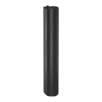
10.5 QFLEX 40 ASSEMBLY
It is recommended that you assemble the column horizontally on a at surface. Lay some cloth or cardboard on the
surface to avoid scratching the surface of the product during the assembly process.
In the hardware pack you will nd two wall brackets and joining hardware consisting of two heavy joining plates with
hinge points, four small link bars and M4 Phillips screws.
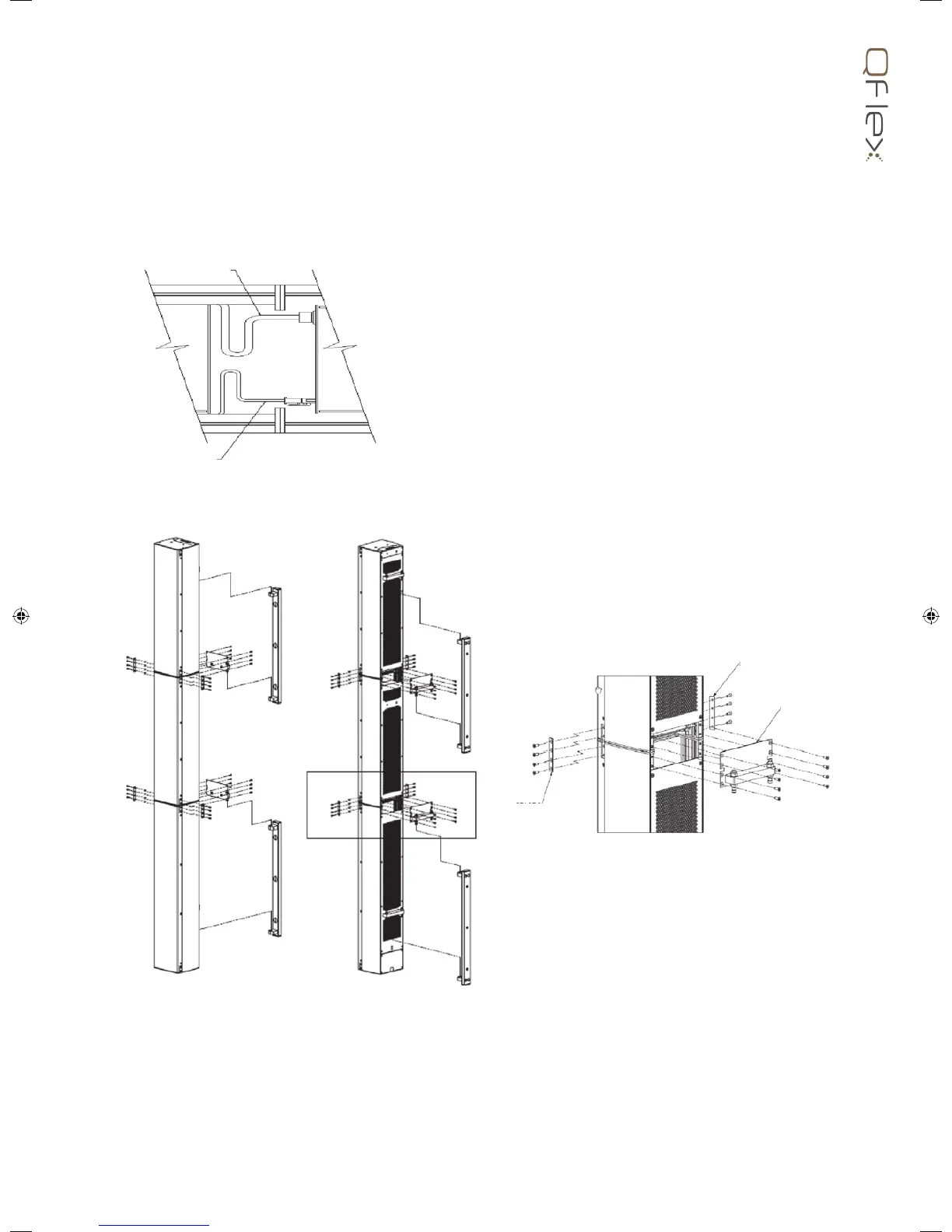
Place each module in its respective position on the assembly area keeping them slightly spaced apart. Take the ying
RJ45 connector in the lower module and insert it into the RJ45 socket in the middle module. Take the ying AC mains
connector in the lower module and insert it into the female connector in the middle module. Take the ying RJ45
connector in the middle module and insert it into the RJ45 socket in the top module. Take the ying AC mains connector
in the middle module and insert it into the female connector in the top module.
Align the three columns together as shown below.
Having the hinge points on either side of the QFlex column allow the loudspeaker to be rotated at 90 degrees to the
mounting structure allowing easy access to the input connector panel.
The installer must ensure that the mounting surface is capable of safely and securely supporting the loudspeaker. Seek
help from architects, structural engineers or other specialists if in any doubt.
Attach the joining plates between each module in
the three stages as shown.
The wall brackets can be hinged on the left or
right pivot points. 3mm Allen grub screws allow the
QFlex 40 to be locked at the desired horizontal angle.
CAT 5
POWER CORD
STAGE 2
STAGE 1
STAGE 3