12
TASCAM Model 24
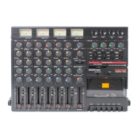
2–Names and Functions of Parts
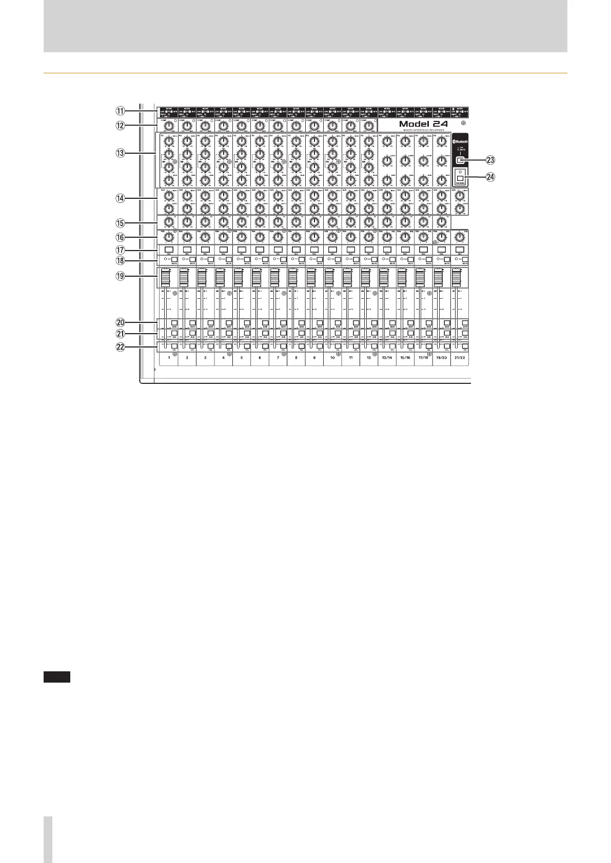
Input channel mixing section
q MODE switches (1-12, 13/14-19/20, 21/22)
Use these to select the input source for each channel.(see “Setting
the MODE switch” on page 26)
w COMP knobs and indicators (1-12)
Use these knobs to adjust the compression of the signals input to
each channel.
When compression is activated, the COMP indicators light.
e EQ knobs (1-12, 13/14-19/20)
i
Use these to boost and attenuate the HIGH, MID and LOW bands
of each channel.
Setting range: ±15 dB
i
The cutoff frequencies of the MID bands can be set for channels
1-12.
Setting range: 100Hz – 8kHz (default: 700Hz)
r MON 1/MON 2 knobs (1-12, 13/14-19/20, 21/22)
Use these to adjust the levels of signals sent to the MONITOR OUT 1/2
buses.
t FX knobs (1-12, 13/14-19/20)
Use to adjust the levels of the signals sent to the FX bus.
y PAN knobs (1-12, 13/14-19/20, 21/22)
Use to adjust the stereo positions of the signals input to each
channel.
NOTE
i
When PAN knobs are centered (C), signals are reduced by 3 dB and
sent to both left and right MAIN MIX L/R buses.
i
When a PAN knob is turned all the way to the left (L), that channel
signal is sent only to the left MAIN MIX L/R bus. It is not sent to the
right bus.
i
When a PAN knob is turned all the way to the right (R), that channel
signal is sent only to the right MAIN MIX L/R bus. It is not sent to the
left bus.
u REC buttons and indicators (1-12, 13/14-19/20, 21/22)
Use these to select the channels to record to the SD card.
i MUTE switches and indicators (1-12, 13/14-19/20, 21/22)
When these switches are on (MUTE indicator lit), those channels are
muted.
o Channel faders (1-12, 13/14-19/20, 21/22)
Use these to adjust the send levels of channel signals.
p MAIN switches (1-12, 13/14-19/20, 21/22)
Turn these switches on to send channel signals to the MAIN MIX L/R
bus.
a SUB switches (1-12, 13/14-19/20, 21/22)
Turn these switches on to send channel signals to the SUB L/R bus.
s PFL switches (1-12, 13/14-19/20, 21/22)
Turn these switches on to send channel signals to the PFL/AFL L/R
bus.
d ON/MUTE switches
Turn this switch on to input audio from a paired Bluetooth device.
f PAIRING button and indicator
Press and hold this button to activate Bluetooth pairing mode.
Press when pairing to end pairing mode.(see “Connecting with Blue-
tooth devices” on page 20)