DC Inverter Air
3.6 Electrical Control and Troubleshooting of Indoor Unit
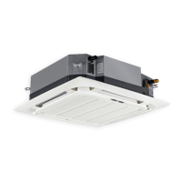
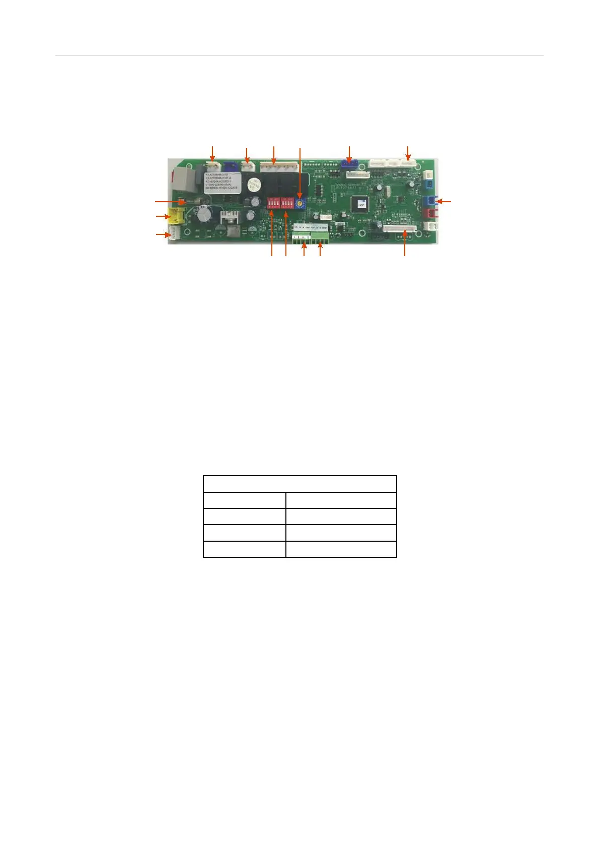
1). Description of Motherboard of Indoor Unit (cassette)
1 2 3 4 5 6
1— Transformer Input socket, 220v high voltage
220V‐240V is inputted to transformer 220V power supply of the power board is inputted to the socket and
transmitted here via fuse and PTC protector.
2—Pump
3—Indoor Fan Output
220V‐240V output, four relays and four wind gears on electric control panel: high wind, middle wind, low
wind and breeze. However, the low‐wind and breeze gear output is short‐circuit, and the breeze gear of
indoor fan has been eliminated, therefore, even though it belongs to the suction of breeze relay, the indoor
fan will be operated as per the low wind gear, that is, there are only three wind speed gears for all indoor air
duct units. It will be operated as per the low wind speed gear even if it is in the heating and anti‐cold wind
and oil‐return period.
4—KNOB1 Indoor Unit Capacity (Model) DIP
5—VERTICAL VANE MOTOR
6—Evaporator Central Temperature Sensor (IPT)
Indoor Ambient Temperature Sensor (RT)
7—WATER SWITCH
8—Dashboard Socket (Display Panel)
The dashboard is only used to display the running status and fault information of the air conditioner, and
receive the signals of the remote controller.
9—Communication Port
Indoor/outdoor units use the RS‐485 communication style for communications, of which, 2 and 3 are used for
communication, with a polarity, and 4 is the shielded layer and it is connected to the position +5V in electric
control panel to enhance the anti‐interference ability of the communication lines. When the indoor/outdoor
units cannot be communicated for continuous 2 minutes, the communication fault will be displayed.
101/ 113
 Loading...