DC Inverter Air
3.4 TCA‐36HRA/DV Electric Control Box (ECB)
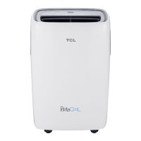
1) ECB Structure of Outdoor Unit
4 3 2 1
1— Power supply terminal block of outdoor unit
Indoor/outdoor communication terminal block
2— Main control panel of outdoor unit
3— Outdoor power filter board
4— Compressor driver module of outdoor unit
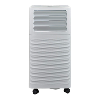
2) Compressor Driver, Fault and Protection
1 2 3 4
1‐ CN708: Communication between compressor driver and main control panel
2‐ U/V/W(CN5, CN6, CN7): Compressor driver output
3‐ AC‐L/AC‐N(CN1, CN2): Power supply input terminal
4‐ L1/L2(CN3,CN4): externally connect PFCDC reactor
5‐ LED Indicator Light
LED701 (Red) OFF: No fault
Flash: shutdown fault indication (see 5.2.1 – List of Shutdown Protection Faults)
LED702 (Yellow) OFF: Not fault
Flash: alarm fault indication (see 5.2.2 – List of Alarm Protections)
LED703 (Green) Flash: Driver standby
91/ 113
 Loading...