DC Inverter Air
Normally ON: Driver running
6‐ LED Indicator Light
LED704(red) Normally ON: Driver is ON
OFF: Driver is OFF
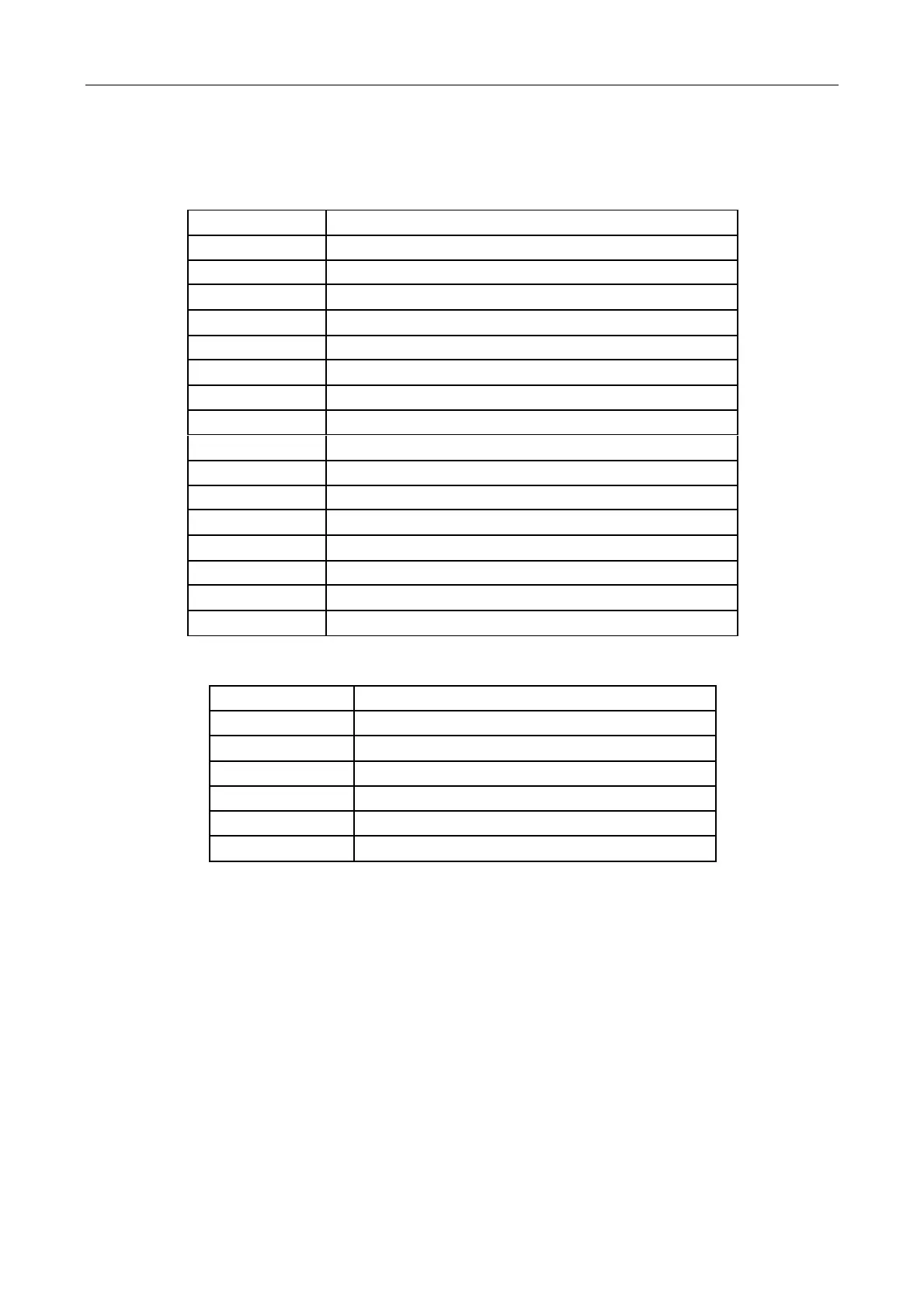
List of Shutdown Protection Faults
Compressor drive failure protection
Compressor over‐current (Peak Value)
Compressor phase current sampling fault
IGBT shell over‐heat shutdown
Input voltage sensor sampling fault
PFC and DSP communication fault
Communication fault of DSP and communication board
Communication fault with main control panel
Note: the “number” in fault code refers to the flashing times of LEDD, etc.
List of Alarm Protections
Compressor over‐current alarm (peak value)
Compressor weak magnetic protection alarm
IGBT shell over‐heat alarm
AC input over‐current alarm
Note: the “number” in fault code refers to the flashing times of LEDD, etc.
3.5 Troubleshooting and Repair
(1) Steps of Fault Repair
A. Collect fault phenomena
B. Judge whether it is a fault or reasonable protection function;
C. Fault identification: determine fault position according to fault display;
D. test the damage condition of failed peripheral elements (sensor, display screen, pressure switch, level switch,
etc.);
E. Replace the damaged parts;
F. Main control panel is damaged or not;
G. Replace the main control panel.
92/ 113
 Loading...