DC Inverter Air
Communication terminal block of indoor/outdoor units
4— Outdoor power supply filter board;
5— Fan capacitor;
6— Electrolytic capacitor
7— Reactor
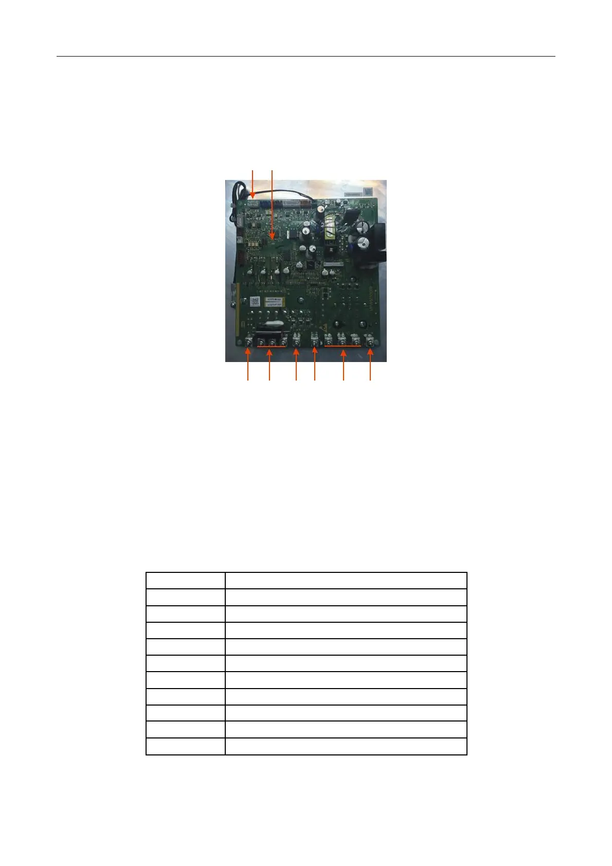
2) Compressor Driver of Outdoor Unit, Fault and Protection
1 2
1— Communication between compressor driver and main control panel
2— LED indicator light (LED601(Red)), Flash(ON for 1s, OFF for1s): Driver runs normally,
Flash (ON for 0.5s, OFF for 0.5s, Flash for N times and OFF for 3.25s; this is a cycle): Module fault
3—DC+ OUT Externally connect the reactor
4—R / S / T 3‐Phase power supply input
Externally connect the capacitor negative electrode
Externally connect the capacitor negative electrode
7—U / V / W Compressor drive output
Externally connect the capacitor positive electrode
List of Shutdown Fault Indications
IPM Over‐current (Peak Value)
Compressor drive failure protection
Compressor over‐current (Peak Value)
Compressor phase current sampling fault
PIM over‐temperature shutdown
PIM temperature sensor fault
DSP and MCU Communication fault
Communication fault with main control panel
Note: the “number” in fault code refers to the flashing times of LEDD, etc.
90/ 113
 Loading...