1) Installation Space
............................................................................................................................
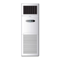
2) FLOOR CONSOLE TYPE
....................................................................................................................
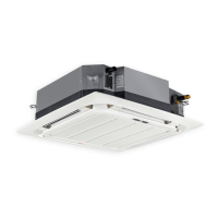
3) UNDER CEILING TYPE
......................................................................................................................
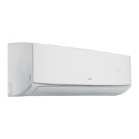
4) Installing indoor unit
.......................................................................................................................
5) DRAINAGE PIPE CONNECTION
........................................................................................................
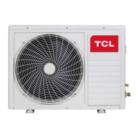
Outdoor Units
.............................................................................................................................................
1.Specification
.........................................................................................................................................................
2 Sound Levels
.........................................................................................................................................................
3 Correction Curve of Capacity performance
..........................................................................................................
1. Correction of Cooling Capacity
...............................................................................................................
2. Correction of Heating Capacity
...............................................................................................................
4. Normal Operation Temperature Range
..................................................................................................
5. Installation Dimension Drawing of Outdoor Unit
................................................................................................
6. Installation Requirements of Outdoor Unit
.........................................................................................................
1. Hoisting and Transportation of Outdoor Unit
.........................................................................................
2. Installation Site of Outdoor Unit
.............................................................................................................
3. Installation Requirements of Side Air Outlet Outdoor Unit
....................................................................
7. Electrical Design
...................................................................................................................................................
Specification of Power Supply
..............................................................................................................
Electrical Wiring Diagram
....................................................................................................................
8. Design and Installation of Connecting Pipes
........................................................................................................
Pipe length and drop height shall comply with the scope required below.
.........................................
Material and Size of the Pipes
.............................................................................................................
Precautions for Installation:
.................................................................................................................
Installation of Refrigerant Pipes
...........................................................................................................
9. Heat Insulation Works
..........................................................................................................................................
Insulation Materials and Thickness
......................................................................................................
Heat Insulation of Refrigerant Pipes
....................................................................................................
Heat Insulation of Drain Pipes
.............................................................................................................
Precautions
..........................................................................................................................................
Maintenance
..............................................................................................................................................
1. Troubleshooting of Inverter System
.....................................................................................................................
8‐way cassette; 4‐way cassette
............................................................................................................
Ceiling & Floor
......................................................................................................................................
Duct
......................................................................................................................................................
2. Fault Identification: Determine the fault type according to the symptom
..........................................................
3. Control System
.....................................................................................................................................................
Overview of Control System
................................................................................................................
Electrical Control of Outdoor Unit and Troubleshooting
.....................................................................
1)
Main Control Board of Outdoor Unit(36K 48K 60K )
..............................................................
2)
Spot‐inspection Description of Outdoor Unit
........................................................................
3)
Display of Fault Codes
.............................................................................................................
18K ,24K outdoor PCB
......................................................................................................................
1‐‐‐ Compressor drive output
,
UVW
..............................................................................................
2‐‐‐ Monitor and test output
...........................................................................................................
 Loading...