7. HYDRAULIC SYSTEM
- 104 -
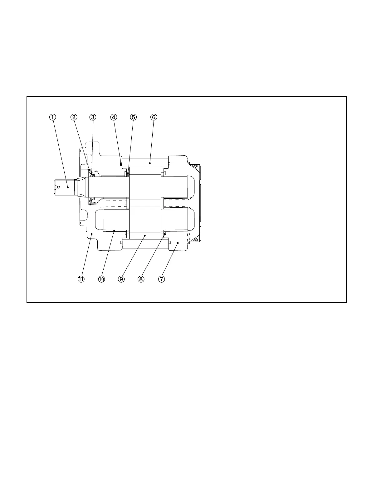
7.1.1 MAIN PUMP
The main pump is a gear type as shown in Fig. 7.1.
The main pump consists of a pump body, a pair of gears, bushings and packings. To minimize the gap
between the gears’ side-faces, pressure-balanced type bearings and lubrication method are used.
The pressure-balanced type directs part of the oil discharged from the main pump into between the
pressure plate and pump body, to press the pressure plate toward the gear side.
1. DRIVE GEAR
2. SNAP RING
3. OIL SEAL
4. GASKET
5. SIDE PLATE
6. PUMP BODY
7. REAR COVER
8. HYPSILOID GASKET
9. DRIVEN GEAR
10. BUSHING
11. FRONT COVER
7.1.2 CONTROL VALVE
The control valve consists of two plunger sections, an outlet section, and an inlet section with a relief
valve as shown in Fig. 7.2. The inlet section relief valve is a cartridge type featuring that its pressure
setting does not change even when it is reinstalled after removed.
Between the inlet section and the lift plunger section and between the lift plunger section and the tilt
plunger section, check valves are installed (two in total).
These check valves serve to prevent the back ow from a heavily loaded section to a lightly loaded
section when the lift and tilt levers are simultaneously operated.
A potentiometer installed on the plunger section at the lift side converts the movement of the plunger
into the voltage and sends it to the controller.
Fig. 7.1 Main Pump