7. HYDRAULIC SYSTEM
- 114 -
7.1.5 FLOW REGULRATOR VALVE
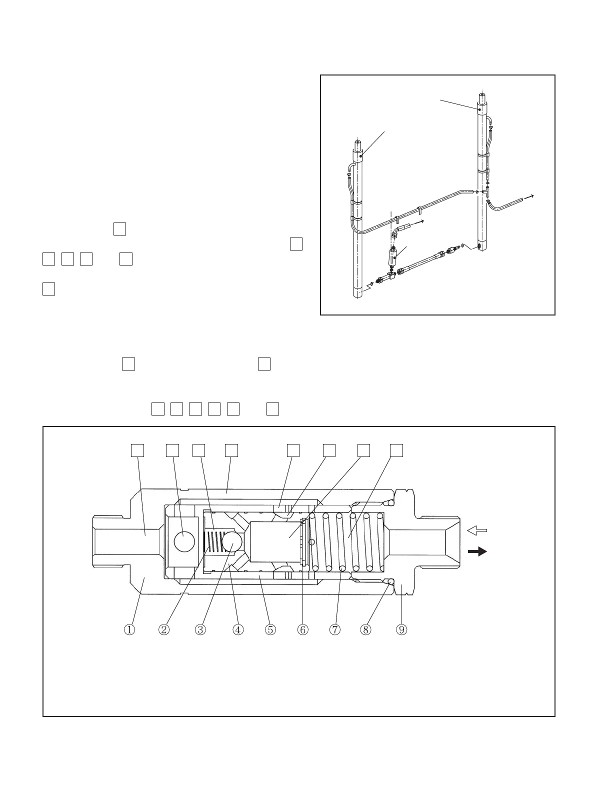
The fl ow regulator valve is located at the position
as shown in Fig. 7.12. It not only controls the fork
lowering speed but works as a safety device in case
of a rupture of the high-pressure hose.
The oil fl owing from the control valve to the lift
cylinders is not controlled, but the oil returning from
the lift cylinders is controlled.
■
Flow regulator valve operation
The oil returning from the lift cylinder fl ows into
the chamber
G
from which it then runs into the
control valve after fl owing through the chambers
F
,
D
,
C
,
B
, and
A
.
In this step, the more the oil flow via the hole
C
in the piston
④
becomes, the larger the pressure
difference between the front and rear of the piston
becomes.
When the force that pushes the piston
④
,
produced by the pressure differential, is greater than the spring force
⑦
, the piston
④
moves to the
right. The hole
D
is narrowed by the hole
C
to limit the fl ow rate, and the fork lowering speed is thus
controlled.
When the forks are raised, the high-pressure oil from the control valve runs into the lift cylinder
through the chambers
A
,
B
,
C
,
D
,
E
, and
F
into the lift cylinder.
FLOW
REGULATOR
VALVE
Fig. 7.12 Mast Piping
1. CASE
2. SPRING
3. BALL
Control valve side
Free fl ow
4. PISTON
5. SLEEVE
6. ORIFICE
7. SPRING
8. “O”-RING
9. NIPPLE
•
Lift cylinder side
•
•
•
•
•
•
•
•
•
•
•
•
•
•
•
•
Regulated
fl ow
LIFT CYLINDER
(RIGHT)
LIFT CYLINDER
(LEFT)
to OIL TANK
to CONTROL
VALVE
Fig. 7.13 Flow Regulator Valve (1.0- to 3.0-ton Trucks)
ABCDEFG H



 To Next Page