- 29 -
3. CONTROL SYSTEM
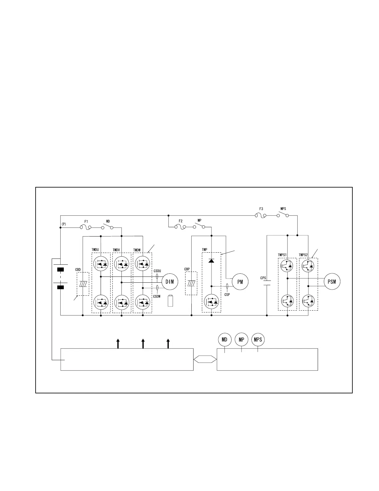
Fig. 3.1 Schematic Diagram of Inverter
3. CONTROL SYSTEM
3.1 GENERAL DESCRIPTION
The control system consists primarily of an inverter assembly which controls the drive motor, a DC
chopper which controls the pump motor, and a PS controller which controls the PS motor.
3.1.1 INVERTER
The inverter converts direct current into 3-phase alternating current. Its schematic diagram is shown
in Fig. 3.1
The inverter consists primarily of a CPU board, a power supply board, and an FET module. Its
schematic diagram is shown in Fig. 3.2.
The CPU board receives signals from the accelerator and others to control the drive motor using the
inverter’s FET module.
The drive motor operating status is monitored by the speed sensor, thermo sensor, and current sensor
and fed back to the CPU board.
POWER MODULE
(3 pcs.)
BATTERY
DRIVE
MOTOR
SPEED SENSOR
POWER
MODULE (1 pc.)
PUMP
MOTOR
POWER
MODULE (2 pcs.)
TMD
GATE
TMP GATE TMPS
GATE
POWER SUPPLY/GATE
DRIVE BOARD
32-BIT CPU BOARD
CAPACITOR
BOARD