- 37 -
3. CONTROL SYSTEM
3.2 MAINTENANCE
3.2.1 TROUBLESHOOTING GUIDE
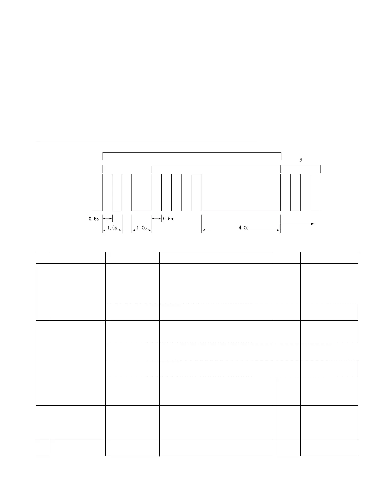
The CPU board of the controller has an LED (green) which shows the content of errors occurring in
the truck, using their corresponding code numbers that are distinguished by different blinking intervals.
Each error code is displayed by a 2-digit decimal number, with both the second and first digits
blinking at an interval of 0.5 seconds while a pause of 1 second OFF is inserted between the second digit
andtherstdigit.Onceanerrorcodeisdisplayed,anOFFperiodof4secondsisinsertedbeforethe
same error code is displayed again. Thereafter, this process is repeated.
If multiple errors occur, the code of the last error detected by the controller is only displayed.
Example: Error code: 23 (Traveling neutral interlock detected)
For errors whose error code is not displayed, refer to the following chart:
The same process
is repeated.
Error code number: 23
LED blinks twice
LED blinks three times
LED comes on
LED goes out
No.
1
2
3
4
Problem
Contactor won’t close
although key switch can
be turned on.
Truck won’t move
or operate (traveling,
load handling and EPS
systems)
CPU board LED of
controller won’t work.
Truck won’t travel
despite FR switch (F or
R) or accelerator pedal
operation.
Truck comes to stop
during traveling.
Hard steering wheel
Error
Harness disconnected
between power supply
board and CPU board
DSW1 improperly set
Reverse connection of
A and B connectors of
speed sensor.
U, V, or W phase wire
broken (missing)
Power module open
Accelerator pedal or
its signal circuit wire
broken
Battery overvoltage
detected
PS motor short-circuited
Remedy
Proceed with remedy in numerical order of encircled numbers.
Repair or change harness between CN1R (power
supply board) and CN9 (CPU board).
Set all DSW1 (2-bit SW) on CPU board to OFF.
Check A and B connectors for connection.
Check DU, DV, and DW cables for breakage, and
repair if needed.
CheckpowermodulesTMDU,TMDV,andTMDW
and repair if needed.
①
Check harnesses between CN2-8,9,20 (CPU
board) and traveling accelerator pedal, and repair
or change if needed.
②
Repair or change accelerator pedal unit.
①
Check battery connectors for contact.
②
Check harness between CN4-2 (CPU board) and
P3 terminal, and repair or change if needed.
③
Check harness between CN4-10 (CPU board)
and P13 terminal.
Check PS motor and wiring for short, and change if
needed.
Reset
Restore to
normal.
Restore to
normal.
Restore to
normal.
Restore to
normal.
Restore to
normal.
Restore to
normal.
Restore to
normal.
Remarks
Use caution when
replacing motor.
Protection is provided if
battery connectors cause
improper contact or get
disconnected during
regeneration.