1. BATTERY AND CHARGER
- 15 -
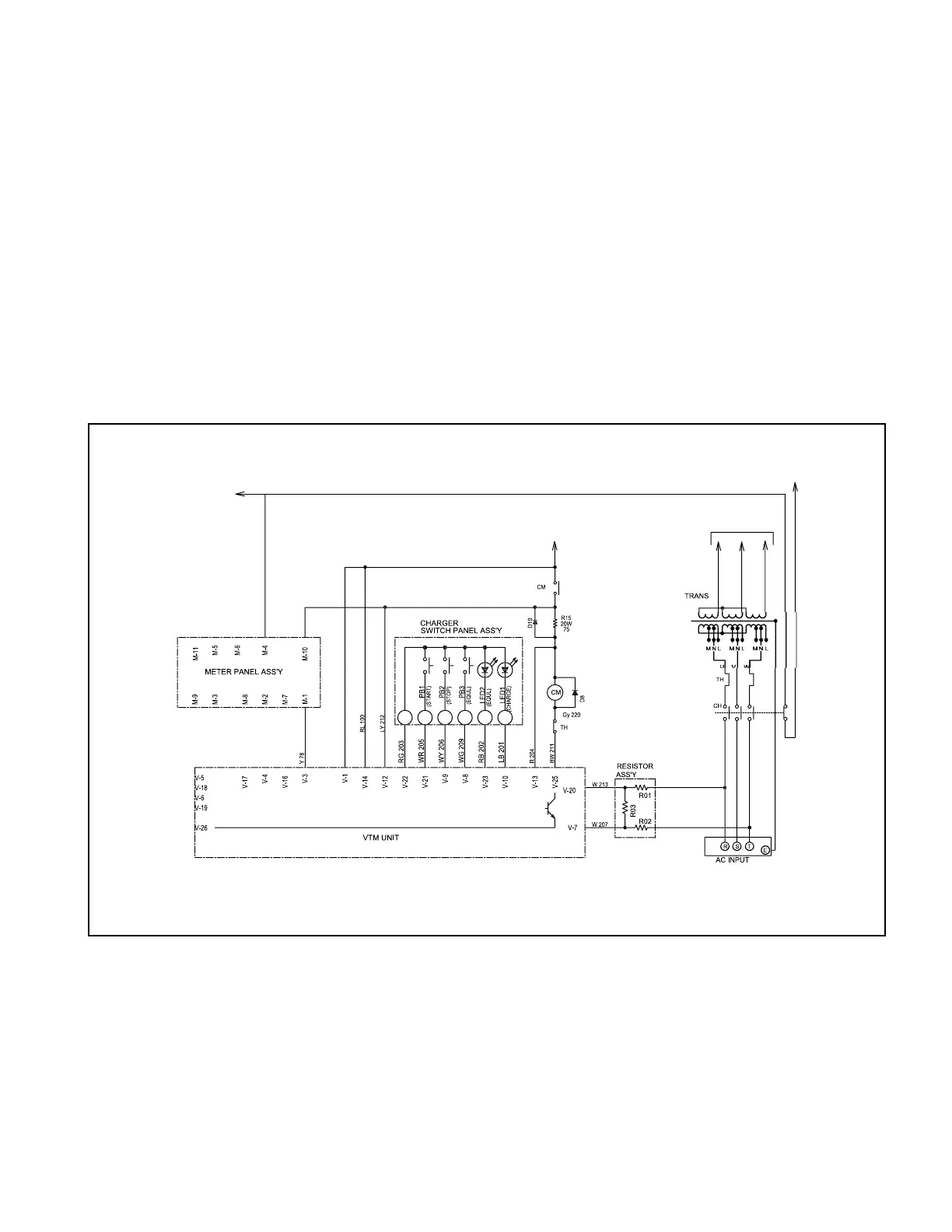
1.1.4 CHARGER OPERATION
(1) When the power switch is turned on, the charger is made ready for operation by the photocoupler in
the VTM unit.
(2) When the START button (PB1) is pressed, a circuit formed through the magnet switch CM, thermal
relay TH, and the terminal V-25 of the VTM unit, and at the same time the battery voltage is applied
for the terminal M-10 of the meter panel. The magnet switch CM is put in action.
(3) When the power is connected to the transformer by the action of the magnet switch CM, LED1
lights up; the fail timer starts counting down the time; and charging operation starts.
The fail timer is set to 15 hours for normal charging.
(4) When the battery voltage rise up to the preset voltage after the charging starts and the
microcomputer in the VTM unit detects the voltage level, the timer starts counting down the time.
The timer is automatically set according to how much the battery has been discharged.
(5) When the time set to the timer expires, the magnet switch CM opens. The charging is now
complete.
KEY SWITCH
Fig. 1.12 Charging Circuit
to CONTROLLER
to FUSE (F4)
to DIODE