8. LOAD HANDLING SYSTEM
- 144 -
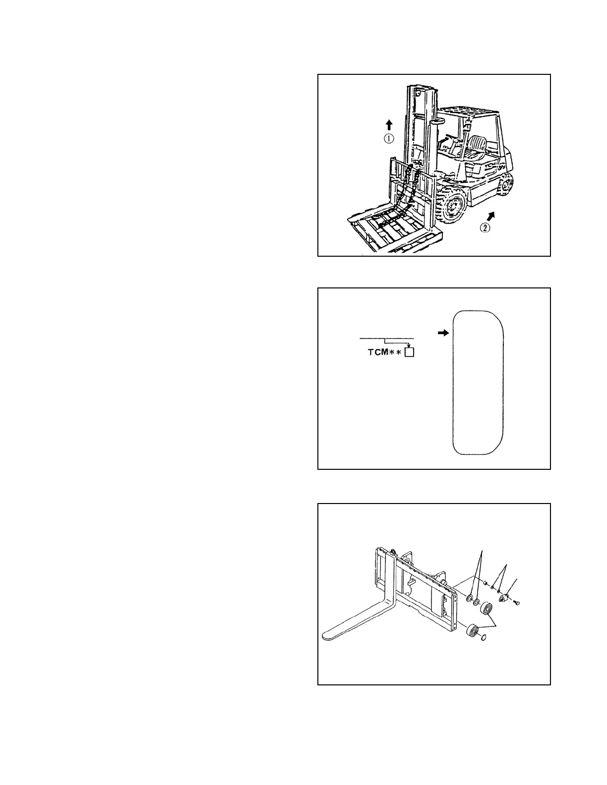
Fig. 8.13
Fig. 8.14
Fig. 8.15
8.2.3
PROCEDURE FOR REPLACING ROLLERS AT CARRIAGE SIDE (excluding VM-77X)
(1) Attach the pallet to the fork and stop the truck
on a level surface.
(2) Lower the fork with the pallet to the ground.
(3) Remove the joint link of the mast side anchor
pin and remove the chain from the sheave.
(4) Extent the lift cylinder rod to raise the inner
channel. (See ① in Fig. 8.13.)
(5) Move the truck backwards after making sure
that the carriage is removed from the inner
channel. (See ② in Fig. 8.13.)
(6) Replacing end rollers
① Remove the lower end roller with a puller,
keeping the shim.
② Install a new end roller with the shim removed
in step ① . Check the stamp of S or SS and
install the roller which is marked the same
stamp, pointing the stamp side to the carriage
side.
③ Remove the snap ring and remove the upper end
roller with a puller.
④ Install a new end roller and secure it with the
snap ring.
(7) Replacing side rollers
① Remove the side roller assembly. Keep the
numbers of the shims and their combination as
they were.
② Install a new roller with the shims removed in
step ① , pointing the groove for the balls to the
shim side. (See Fig. 8.16.)
③ If there is excessive looseness between the side
roller and inner channel, and the shims between
the end roller and side roller, seeing “8.2.5
PROCEDURE FOR ADJUSTING SHIMS”.
END
ROLLER
Stamp (S or SS)
SHIM
SIDE
ROLLER
SHIM
 Loading...

