3. CONTROL SYSTEM
- 34 -
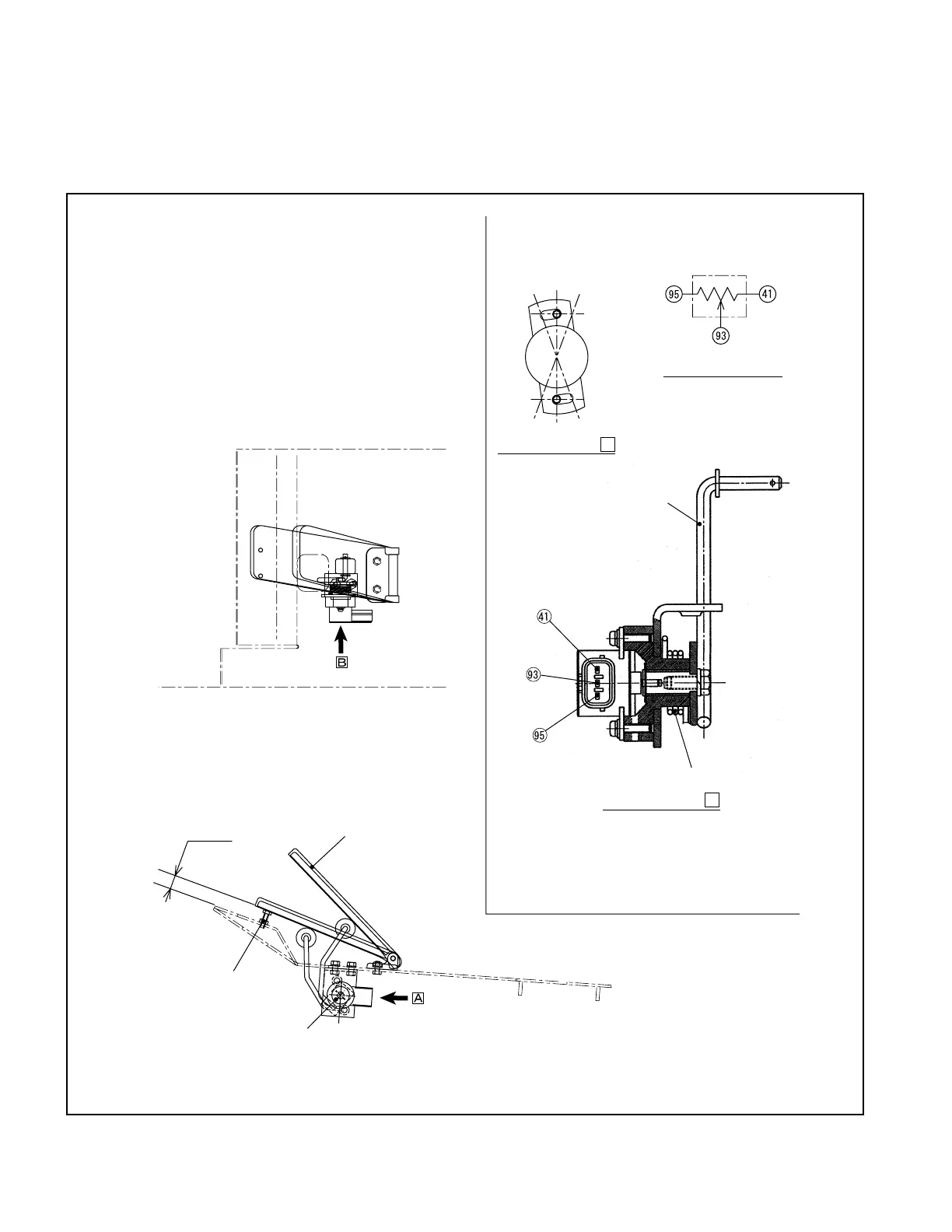
3.1.2 ACCELERATOR PEDAL
The accelerator pedal is installed as shown in Fig.3.6, and the amount of accelerator pedal effort is
transmitted to the potentiometer.
The potentiometer converts pedal effort into voltage change and sends it to the controller.
1. Apply a voltage of +5 ±0.01 V between 95 and 41.
2. Turn potentiometer clockwise in neutral state and lock it at a
position at which the voltage between 93 and 41 shows 0.1 V
± 0.1 V.
3. Move the lever a few times and make sure the voltage
between 93 and 41 shows 2.7 V ± 0.2 V in full-throttle state.
18.5 mm
[0.73 in.]
PEDAL
STOPPER
POTENTIOMETER
LEVER
SPRING
Connection diagram
Fig. 3.6 Accelerator Pedal
View looking from
B
View looking from
A