7. HYDRAULIC SYSTEM
- 115 -
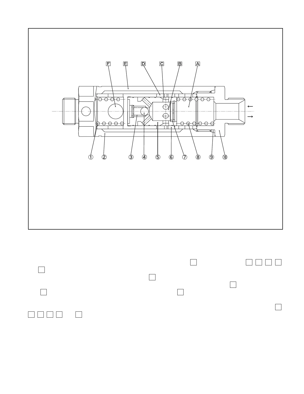
Fig. 7.14 Flow Regulator Valve (3.5-ton Trucks)
■
Flow regulator valve operation
The oil returning from the lift cylinder ows into the chamber
F
, past the chambers
E
,
D
,
C
,
B
,
and
A
, and then back into the control valve.
In this step, the more the oil ows via the hole
C
in the piston
⑤
, the greater the pressure differential
across the piston
⑤
becomes to shift the piston
⑤
to the right. Therefore, the hole
D
is narrowed by the
hole
C
so that the quantity of oil owing through the hold
D
is restricted to reduce the fork lowering
speed.
When the forks are raised, the high-pressure oil from the control valve ows through the chambers
A
,
B
,
C
,
D
,
E
, and
F
to the lift cylinders.
1. SPRING
2. CASE
3. SPRING
4. BALL
5. PISTON
6. SLEEVE
7. ORIFICE
8. SPRING
9. “O”-RING
10. NIPPLE
Control valve side
Lift cylinder side
Free ow
Regulated
ow
 Loading...

