7. HYDRAULIC SYSTEM
- 106 -
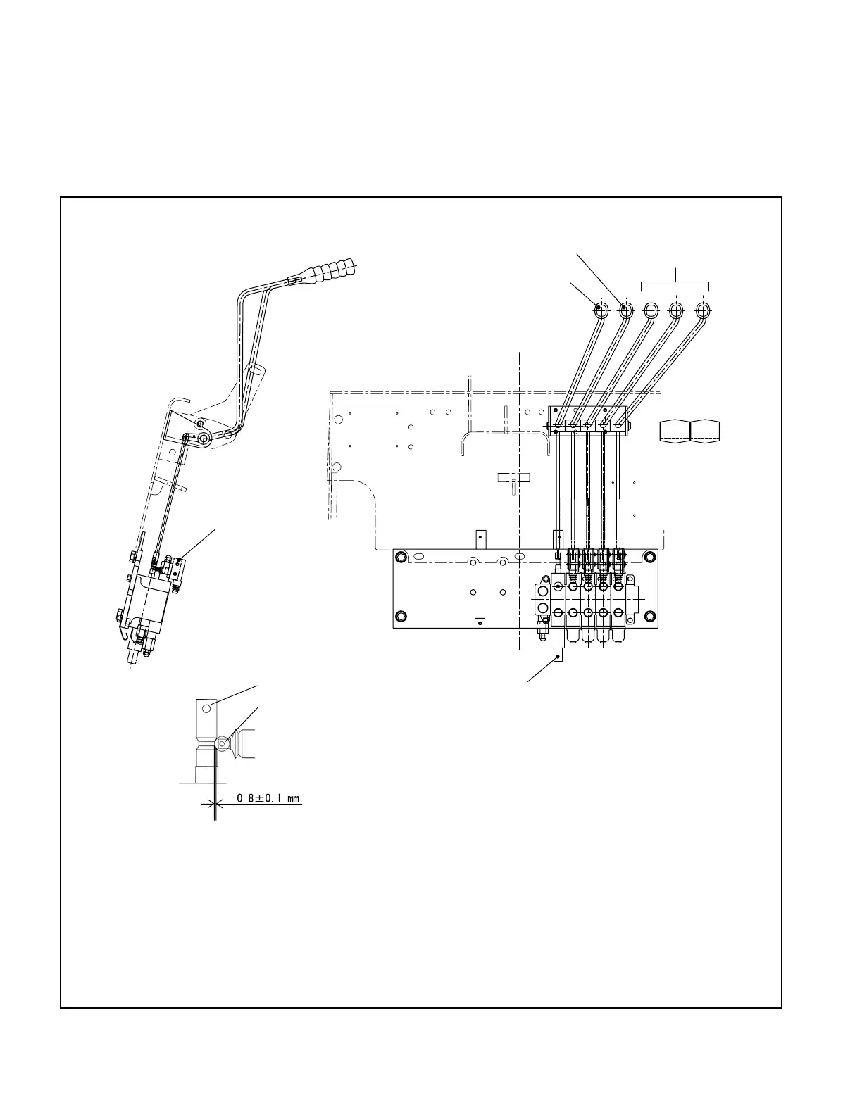
(1) Valve control
The control valve plungers are operated with the levers shown in Figure 7.3, with each of the levers
installed on a single shaft.
The bracket supporting each shaft is attached to the front guard. The movement of each lever is
transmitted through the rod to the corresponding plunger.
TILT LEVER
LIFT LEVER
ATTACHMENT LEVERS
(OPTIONAL)
POTENTIOMETER
VALVE SWITCH
VALVE SPOOL
PLUNGER
(0.031±0.0039 in.)
Fig. 7.3 Valve control
○
Installing the valve switch
Install the valve switch so that it turns on when the plunger is pushed in 0.8 ±0.1 mm
[0.031 ±0.0039 in.].
At this time, the center of switch’s plunger is aligned with the center of the cam.