19
83488001 Revision N
5. CONTROLS, INDICATORS, CONNECTORS
5.1. Front Panel Layout (L Model)
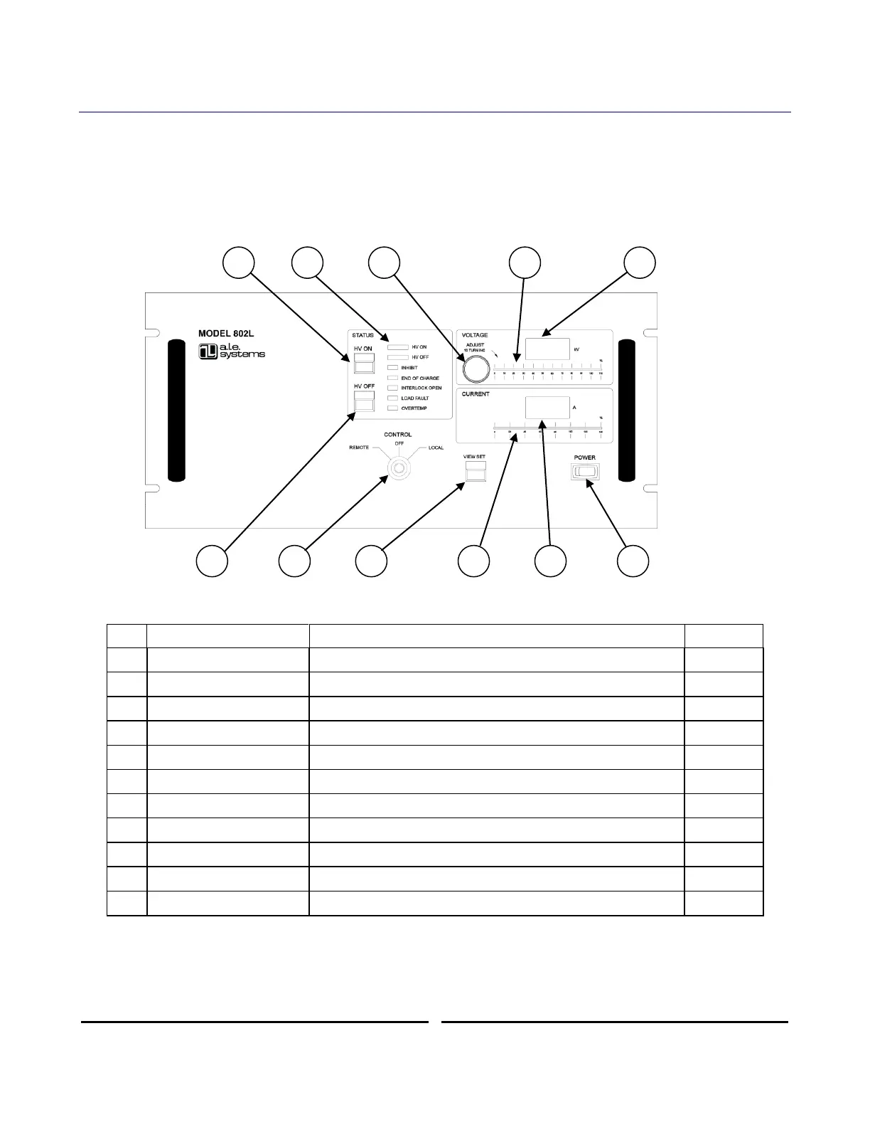
The 802L series power supply is equipped with a fully instrumented front panel featuring
output voltage control, voltage and current metering, and comprehensive status LEDs, along
with local/remote mode keyswitch, and power on switch. The 802L can be operated locally
from the front panel or remotely via the control connector located on the rear panel (see
Section 6.2). Front panel layout of the 802L power supply is shown in Figure 3 below.
Figure 6 802L Front Panel Controls and Indicators
Indicates status of supply and presence of any faults
10 turn pot for setting output voltage in local mode
Analog bar graph showing output voltage (%)
Digital display of output or set voltage
Switches control between remote, local, and off modes
Push to view the output voltage set point in local mode
Analog bar graph showing average output current (%)
Digital display of average output current
Turns on/off power to auxiliary circuits
Table 3 Front Panel Controls and Indicator Functions (L Model)
The front panel controls/indicators are described in detail in the following sections.