31
83488001 Revision N
Table 6 802 Remote Interface Description
Note 1 – For 802L or 802S models, the front panel LEDs are driven by open collector drivers
that are common to the remote control interface indicator signals. A pullup resistor is not
required to sense the remote interface voltage on these signals. The user should expect the
Active logic level (low) to be between 2 and 4V. If an external pullup resistor is added, the
Active logic level (low) voltage will be higher.
For 802-OEM models, a pullup resistor is required to sense voltage levels at these outputs.
For applications that require logic level inputs the use of an opto-isolation device is
recommended.
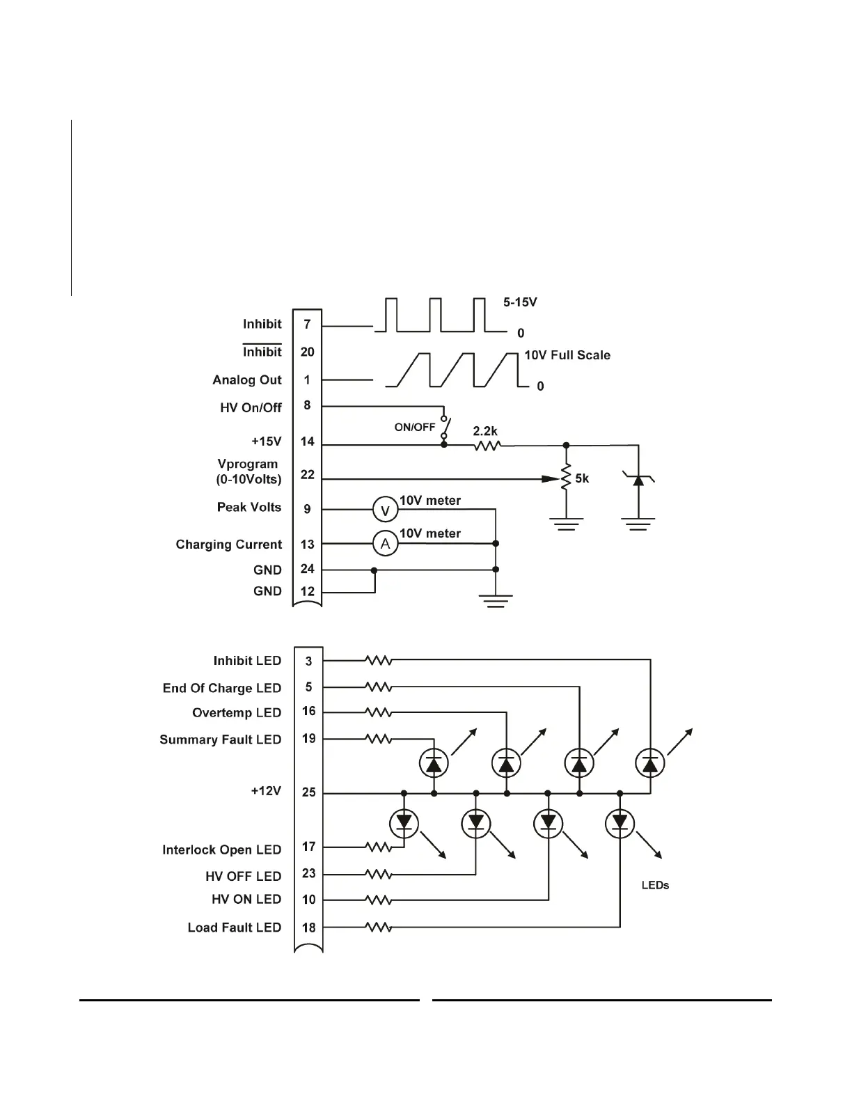
Figure 12 Suggested external remote interface circuit.