30
83488001 Revision N
circuitry will interrupt the power supply's operation causing it to turn OFF. For a full
explanation of each control and indicator refer to Section 5.
6.2. Remote Operation (All models)
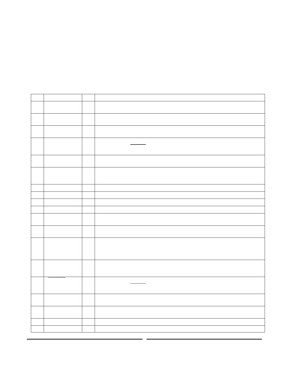
All 802 models are easily controlled through the 25 pin sub D-type remote interface
connector located on the rear panel. The minimum required signals for remote control
operation are; HV ON/OFF, Vprogram and GND. The remaining signals are provided for
status monitoring and fault diagnosis, or more sophisticated control methodologies. The
function each signal is shown in Table 6, with a schematic showing a suggested remote
interface circuit shown in Figure 12.
0-10V (±1%) Analog of output voltage waveform. Impedance 1kIf the 5V option is
installed the voltage level is 0-5V.
Open collector through 100. Low impedance when INHIBIT signal applied. See Note
1.
Open collector through 100. Low impedance when power supply reaches End of
Charge. See note 1.
5-15V Inhibits unit, open or ground allows operation. Input impedance >10kNote use
either INHIBIT or INHIBIT, never both signals. Do not use the INHIBIT BNC as well as
the INHIBIT signal.
15V=On, ground or open =Off. Also used to reset latching faults by cycling from On to
Off. Input impedance >1M If the EN option is installed 15V=Off, Ground or open = On
0-10V (±1%) Peak detector of output voltage waveform. Can be used to drive a meter
displaying peak charging voltage. Impedance 10k. If the 5V option is installed the
voltage level is 0-5V.
Open collector through 100. Low impedance when HV output is enabled. See Note 1.
Control circuit return. Also chassis/earth ground.
Uncalibrated Analog of output current waveform. Impedance 10k
Open collector through 100. Low impedance when inverter over temperature
condition occurs. See Note 1.
Open collector through 100. Low impedance when external interlock circuit is open.
See Note 1.
Open collector through 100. Low impedance when load fault condition occurs. Load
fault is normally a non-latching fault and will self-reset after approximately 500ms,
unless caused by an output overvoltage where the supply will latch off. For models with
the LP option, an external RESET cycle is required to restart the unit. See Note 1.
Open collector through 100. Low impedance indicated a summary fault condition.
Summary fault is a logical OR of Overvoltage, Overtemp, AC Line, and Open Interlock
conditions. See Note 1.
0V Inhibits unit, 15V or open allows operation. Input impedance >10 kNote use
either INHIBIT or INHIBIT, never both signals. Do not use the INHIBIT BNC as well as
the INHIBIT signal.
0-10V = 0-100% of rated output voltage. Input impedance >1M. If the 5V option is
installed the voltage level is 0-5V.
Open collector through 100. Low impedance when HV output is off/disabled. See
Note 1.
Control circuit return. Also chassis/earth ground.