Rear Panel
TEAC CD-RW Drive User’s Manual 5
Rear Panel
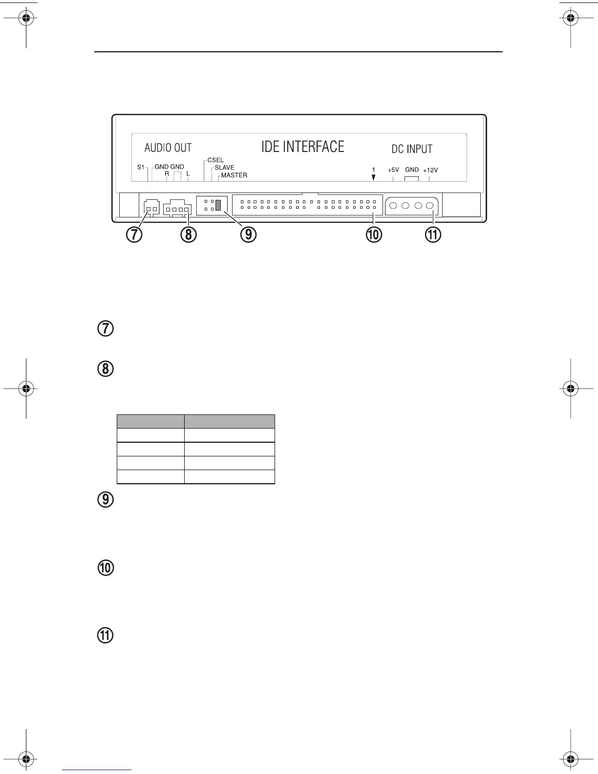
Figure 3 illustrates the rear panel of the CD-RW Drive.
Figure 3. Rear Panel of the CD-RW Drive
digital audio connector:
You can connect a digital audio cable to this digital
signal output connector.
analog audio output connector:
You can use the included analog audio
cable to connect this connector to the audio input connector on a sound card.
Pin assignments are described in the following table:
CSEL/Slave/Master configuration jumper:
The CD-RW drive includes
three pairs of jumper pins on the rear panel that allow you to set the drive to
CSEL, Slave, or Master mode. (For more information, see“Configuring the
CD-RW Drive” and Figure 5 on page 7.)
interface connector:
Use the included IDE interface ribbon cable to connect
the CD-RW drive to an IDE interface in your computer. (For more
information, see “Installing the CD-RW Drive” on page 8 and Figure 7 on
page 9.)
power connector:
Connect the power connector to the +5VDC and +12VDC
power sources. The +5VDC terminal is on the left as you face the rear panel;
the +12VDC terminal is on the right. The two center terminals are ground
terminals. (For more information, see “Installing the CD-RW Drive” on
page 8 and Figure 7 on page 9).
Pin Number
Audio Signal
1 Left signal
2Ground
3Ground
4Right signal
CSEL/Slave/Master interface
connector
power
connector configuration jumper
analog audio
connector
digital audio
connector
TEAC52x24x52.book Page 5 Thursday, December 19, 2002 3:29 PM