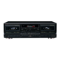
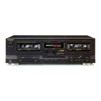
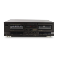
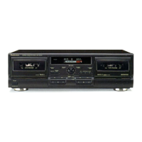
RS・TR575
Pin
No.
Mark
1O
Division
Func竜ion
Check poin量
※Discription
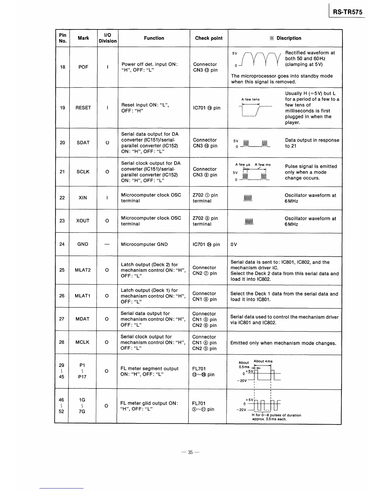
18
POF
1
Power Qff det.input ON:
H,OFF=L
Connector
CN3⑫pin
5v Rectified waveform at
both50and60Hz
o (clamping at5V)
The microprocessor goes into standby mode
when this signal is removed,
19
RESET
1
Reset input ON:L,
OFF:H
lC701⑲pln
一
Usuay H(ニ5V)but L
A few tens fOr a period Of a few to a
1
〆
few tens of
miiseconds is first
plugged in when the
player.
20
SDAT
O
Serial data output for DA
converter(IC151)serial−
Parael converter(IC152)
ON:HOFF:L
,
Connector
CN3⑩pin
51」欄 器outputin「esponse
21
SCLK
0
Serial clock output for DA
converter(IC151)1seria卜
Parallel converter(IC152)
ON:H,OFF:L
Connector
CN3⑨pin
A fewμs Afewms pulse slgnal is emitted
5v鵠 。nlywhenam。de
。」欄 Change・CCUrS.
22
XlN
1
Microcomputer cbck OSC
terminal
Z702①pin
terminaI
㎜ 繍lato「wavefo「mat
23
XOUT
O
Microcomputer clock OSC
terminaI
Z702③pin
terminal
㎜ 繍lato「wavefo「mat
24
GND
一
Microcomputer GND
lC701⑭pin
OV
25
MしAT2
O
Latch output(Deck2)for
mechanismcontrolON=H,,
OFF:L
Connector
CN2⑦pin
Serial data is sent to:IC801,IC802量and the
mechanism driver IC.
Select the Deck2data from this serial data and
Ioad it into IC802.
26
MLAT1
0
Latch output(Deck1)for
mechanism control ON:H,
OFF:L
Connector
CN1⑥pin
Select the Deck l data from the serial data and
Ioad it into IC801.
27
MDAT
0
Serial data output for
mechanism control ON=H,
OFF:L
Connector
CN1⑤pin
CN2⑥pin
Serial data used tocontrol the mechanism driver
via IC801and IC802.
28
MCLK
0
Serial clock output for
mechanism control ON=H,
OFF=L
Connector
CN1④pin
CN2⑤pin
Emitted only when mechanism mode changes.
29
〜45
P1
〜
P17
0
FL meter segment output
ON:H,OFF:L
FL701
⑫〜⑳pin
0.5ms
+5V
O
−20V
About Ab・ut4ms
46
〜52
1G
〜
7G
0
FL meter glid output ON:
H,OFF:L
FL701
⑤〜⑪pin
+5V
O
−20V−
H
一
for O〜8pulses of dura塾ion
approx.0.5ms each。
一35一