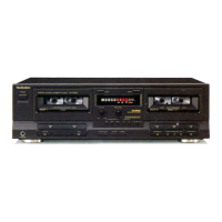
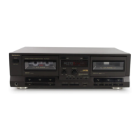
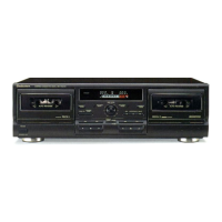
RS・TR575
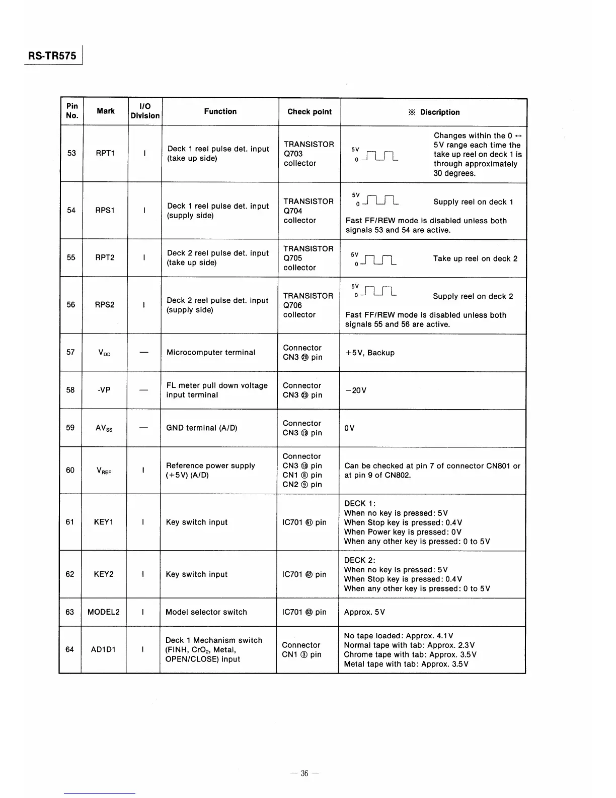
Pin
No.
Mark
1O
Division
Func量lon
Check poin量
※Disc巾tion
53
RPT1
1
Deck l reel puIse det.input
(take up side)
TRANSISTOR
Q703
coIlector
Changes within theO←・
5V range each time the
5V
。一rLrL takeup「eel・ndecklis
through apProximately
30degrees.
54
RPS1
1
Deck l reel pulse det.input
(supply side)
TRANSISTOR
Q704
coector
51∫Uエ SuppIyreel。ndeckl
Fast FF/REW mode is disabIed unless both
signals53and54are active,
55
RPT2
1
Deck2reel pulse det.input
(take up side)
TRANSISTOR
Q705
coector
5V。∫しrL Takeup「eel・ndeck2
56
RPS2
匪
Deck2reel pulse det.input
(supply side)
TRANSISTOR
Q706
coector
5ざ皿 Supp監yreel。ndeck2
Fast FFREW mode is disabled unless both
signals55and56are active.
57
VDD
一
Microcomputer terminal
Connector
CN3⑳pin
+5V,Backup
58
・VP
一
FL meter pudown voltage
input terminaI
Connector
CN3⑬pin
一20V
59
AVss
一
GND terminal(A/D)
Connector
CN3⑩pin
OV
60
VREF
聾
Reference power supPly
(+5V)(A/D)
Connector
CN3⑱pin
CN1⑧pin
CN2⑨pin
Can be checked at pin70f connector CN8010r
at pin90f CN802.
61
KEY1
1
Key switch input
lC701⑪pin
DECK1:
When no key is pressed:5V
When Stop key is pressedl O.4V
When Power key is pressed:OV
When any other key is pressed:O to5V
62
KEY2
1
Key swltch input
lC701⑫pin
DECK2:
When no key is pressedl5V
When Stop key is pressed:0.4V
When any other key is pressed:O to5V
63
MODEL2
1
Model selector switch
IC701⑬pin
Approx.5V
64
ADI D1
1
Deck l Mechanism swltch
(FINH,CrO2,Metal,
OPEN/CLOSE)input
Connector
CN1③pin
No tape loaded:ApProx.4.1V
Normal tape with tab:Approx.2.3V
Chrome tape with tab:Approx.3.5V
Metal tape with tab=Approx.3.5V
一36一