26
6.7. DC MOTOR UNIT
1. Remove the T/T RUBBER MAT and TURNTABLE UNIT.
(See 6.3. T/T RUBBER MAT, TURNTABLE UNITT,
step1.)
2. Remove the INSULATORS.
(See 6.5. INSULATORS, step2 and 3.)
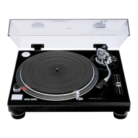
3. Remove the BOTTOM CHASSIS.
(See 6.6. BOTTOM CHASSIS, step3 and 4.)
4. Remove the coupler and screws for removal.
• Coupler: P3101
• Screw: RHD30248 [0.55 - 0.75 N•m] (3)
5. Put the unit back to the original place.
6. Separate the dust cover unit and the cabinet ass'y, and
then remove the DC MOTOR UNIT.
6.8. TONE ARM UNIT, QUEUING
KNOB, ARMREST UNIT
[Removing the TONE ARM UNIT]
1. Remove the T/T RUBBER MAT and TURNTABLE UNIT.
(See 6.3. T/T RUBBER MAT, TURNTABLE UNIT, step1.)
2. Remove the INSULATORS.
(See 6.5. INSULATORS, step2 and 3.)
3. Remove the BOTTOM CHASSIS.
(See 6.6. BOTTOM CHASSIS, step3 and 4.)
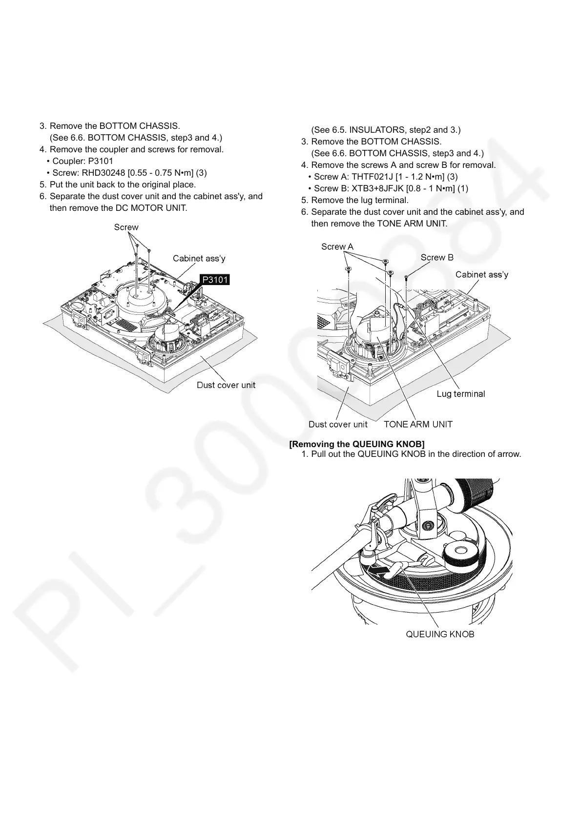
4. Remove the screws A and screw B for removal.
• Screw A: THTF021J [1 - 1.2 N•m] (3)
• Screw B: XTB3+8JFJK [0.8 - 1 N•m] (1)
5. Remove the lug terminal.
6. Separate the dust cover unit and the cabinet ass'y, and
then remove the TONE ARM UNIT.
[Removing the QUEUING KNOB]
1. Pull out the QUEUING KNOB in the direction of arrow.