29
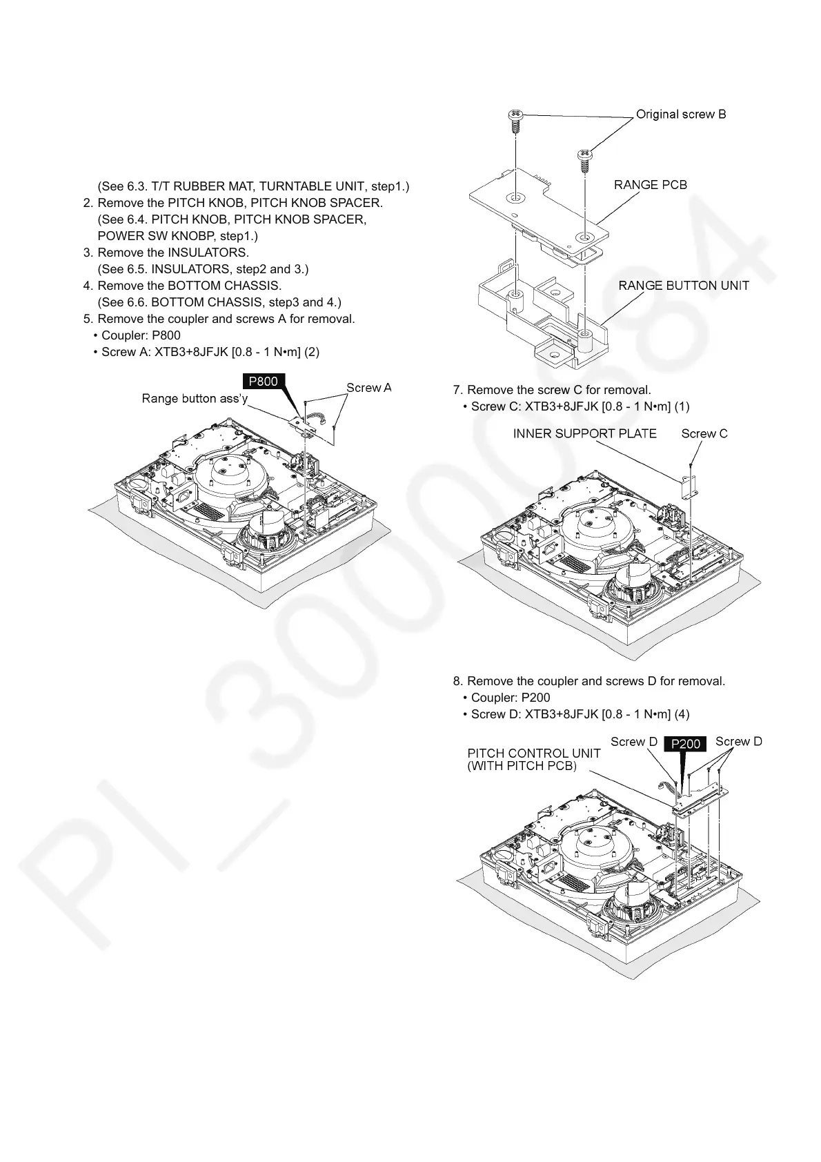
6.11. RANGE PCB, RANGE BUTTON
UNIT, INNER SUPPORT PLATE,
PITCH CONTROL UNIT (WITH
PITCH PCB)
1. Remove the T/T RUBBER MAT and TURNTABLE UNIT.
(See 6.3. T/T RUBBER MAT, TURNTABLE UNIT, step1.)
2. Remove the PITCH KNOB, PITCH KNOB SPACER.
(See 6.4. PITCH KNOB, PITCH KNOB SPACER,
POWER SW KNOBP, step1.)
3. Remove the INSULATORS.
(See 6.5. INSULATORS, step2 and 3.)
4. Remove the BOTTOM CHASSIS.
(See 6.6. BOTTOM CHASSIS, step3 and 4.)
5. Remove the coupler and screws A for removal.
• Coupler: P800
• Screw A: XTB3+8JFJK [0.8 - 1 N•m] (2)
6. Remove the original screws B for removal.
• Original screw B: XTB3+8JFJK [0.8 - 1 N•m] (2)
7. Remove the screw C for removal.
• Screw C: XTB3+8JFJK [0.8 - 1 N•m] (1)
8. Remove the coupler and screws D for removal.
• Coupler: P200
• Screw D: XTB3+8JFJK [0.8 - 1 N•m] (4)