32
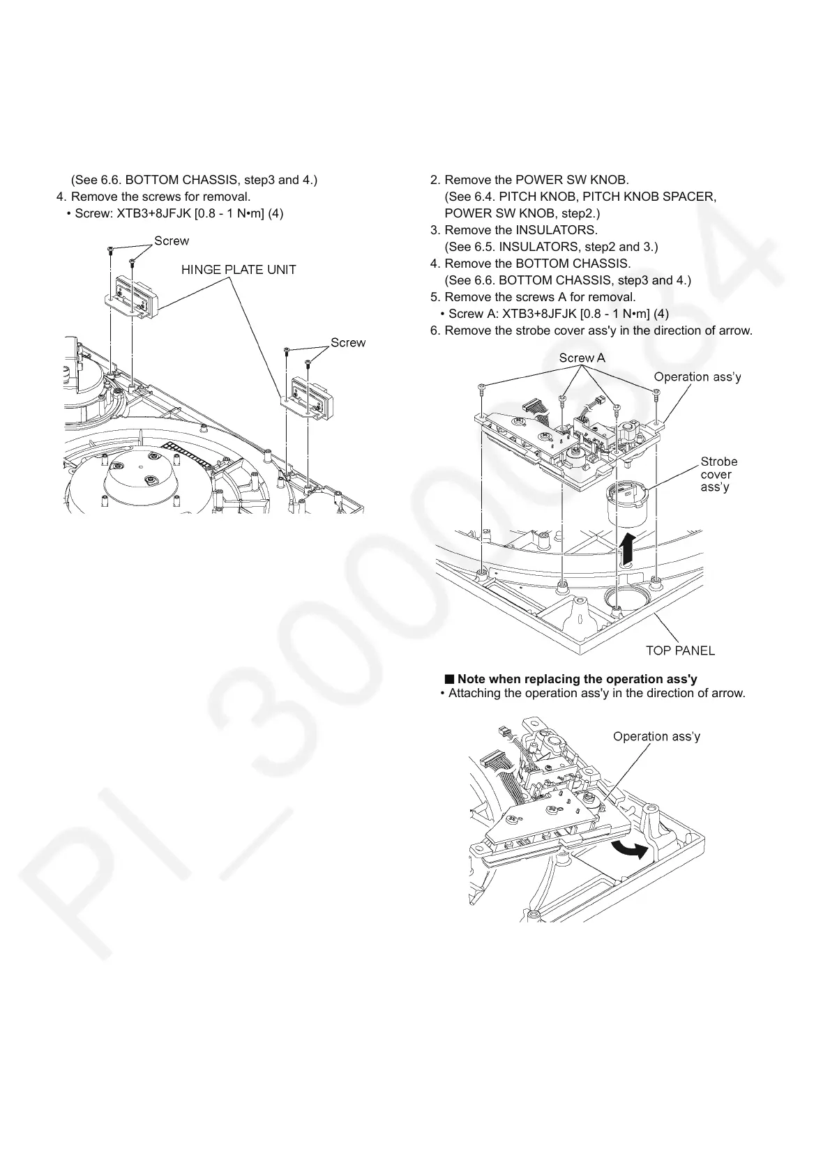
6.15. HINGE PLATE UNIT
1. Remove the T/T RUBBER MAT and TURNTABLE UNIT.
(See 6.3. T/T RUBBER MAT, TURNTABLE UNIT, step1.)
2. Remove the INSULATORS.
(See 6.5. INSULATORS, step2 and 3.)
3. Remove the BOTTOM CHASSIS.
(See 6.6. BOTTOM CHASSIS, step3 and 4.)
4. Remove the screws for removal.
• Screw: XTB3+8JFJK [0.8 - 1 N•m] (4)
6.16. SW PCB, PANEL PCB, STROBE
PCB, OPERATION UNIT, TOP
PANEL
1. Remove the T/T RUBBER MAT and TURNTABLE UNIT.
(See 6.3. T/T RUBBER MAT, TURNTABLE UNIT, step1.)
2. Remove the POWER SW KNOB.
(See 6.4. PITCH KNOB, PITCH KNOB SPACER,
POWER SW KNOB, step2.)
3. Remove the INSULATORS.
(See 6.5. INSULATORS, step2 and 3.)
4. Remove the BOTTOM CHASSIS.
(See 6.6. BOTTOM CHASSIS, step3 and 4.)
5. Remove the screws A for removal.
• Screw A: XTB3+8JFJK [0.8 - 1 N•m] (4)
6. Remove the strobe cover ass'y in the direction of arrow.
Note when replacing the operation ass'y
• Attaching the operation ass'y in the direction of arrow.