28
6.10. STYLUS LIGHT UNIT (WITH
LED PCB), STYLUS SW PCB
1. Remove the T/T RUBBER MAT and TURNTABLE UNIT.
(See 6.3. T/T RUBBER MAT, TURNTABLE UNIT, step1.)
2. Remove the INSULATORS.
(See 6.5. INSULATORS, step2 and 3.)
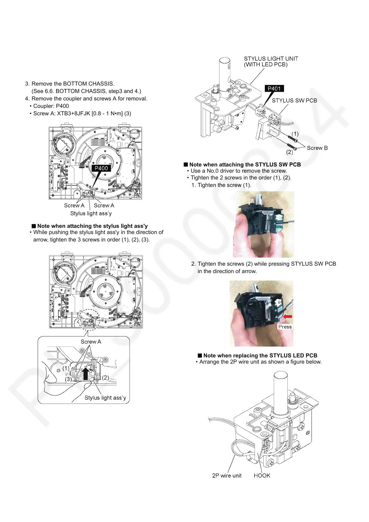
3. Remove the BOTTOM CHASSIS.
(See 6.6. BOTTOM CHASSIS, step3 and 4.)
4. Remove the coupler and screws A for removal.
• Coupler: P400
• Screw A: XTB3+8JFJK [0.8 - 1 N•m] (3)
Note when attaching the stylus light ass'y
• While pushing the stylus light ass'y in the direction of
arrow, tighten the 3 screws in order (1), (2), (3).
5. Remove the coupler and screws B for removal.
• Coupler: P401
• Screw B: XSN2+10FJ [0.1 - 0.3 N•m] (2)
Note when attaching the STYLUS SW PCB
• Use a No.0 driver to remove the screw.
• Tighten the 2 screws in the order (1), (2).
1. Tighten the screw (1).
2. Tighten the screws (2) while pressing STYLUS SW PCB
in the direction of arrow.
Note when replacing the STYLUS LED PCB
• Arrange the 2P wire unit as shown a figure below.