RUN PERSONAL: Service & maintenance manual - rev. 3.1
Page 3.16
3.16. EMERGENCY STOP SIGNAL MANAGEMENT
The device consists of 2 magnetic sensors connected in parallel, fitted on the machine display, and
a switch containing two magnets which, depending on whether or not it is positioned on the sensors,
varies the state of the signals output by the sensors to the Display Board.
3.16.1. CONTROL LOGIC
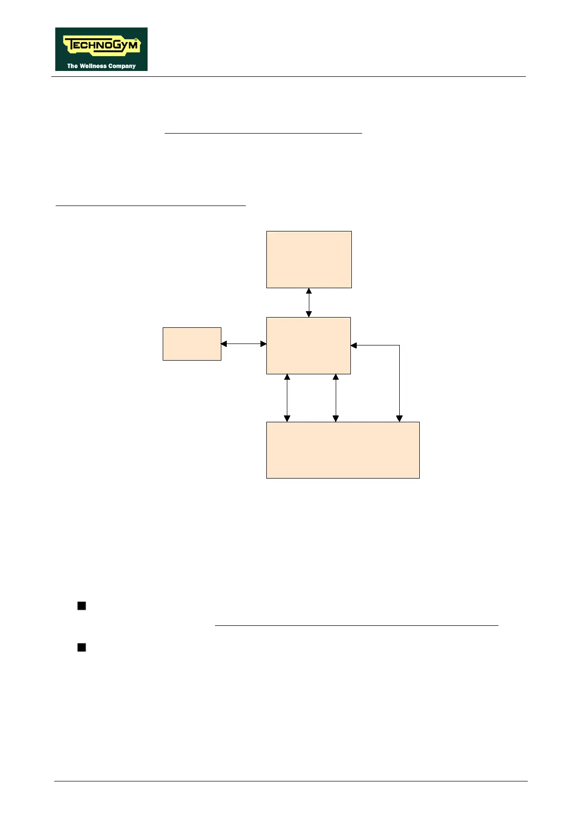
The control block diagram is as follows:
Emergency
Display
Board
RS-485
CN22
Keyboard
Driver
Reset
Emergency
Key
Contact
CN17
J3A
When the user detaches the emergency stop device, the NC contact of the sensors is opened,
changing the state of the two signals output by them to the Display Board. Each of the two sensors
outputs a distinct signal, interpreted as follows: one is an “SW Emergency” signal, and one is an
“HW Emergency” signal.
The two signals are managed as follows:
SW Emergency: The Display Board detects the emergency condition and signals it by
displaying the message “Reposition the emergency stop device and touch the screen” and
sends the information to the drive over the 485 serial link to halt the motors..
HW Emergency: The Display Board sends the emergency signal directly to the drive to
halt the motors.
To reinstate the machine's operation, it is necessary to reposition the emergency stop device on the
control panel and press any key on the display, as prompted.
 Loading...


