© Technosoft 2007 19 IBL2403 Technical Reference
T E C H N O S O F T
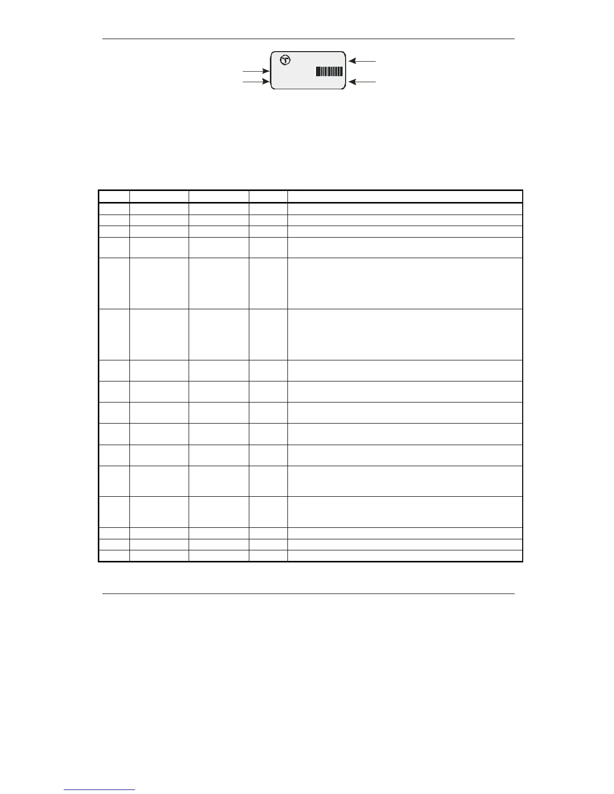
AB1234
Drive Name
Article Number
Serial Number
Manufacturer
Figure 3.6. IBL2403-CAN (CANopen execution for Step motors with incremental encoder ) Identification
Label
3.2.3. J1 Connector pinout
Pin
Pin name TML name Type Function/Alternate function/ Comments
1
+V
DC
- I
• Positive terminal of the motor supply: 12 to 28V
DC
2
GND
- -
• Ground
3
+5V
OUT
- O
• 5V output (internally generated)
4
Ref
AD5
I
• Unipolar 0 V…+5 V analog input. May be used as
analog position, speed or torque reference.
5
Pulse
IN#38 /
PULSE
I
• 5V or 24V compatible digital input
• Can be used as PULSE input in Pulse & Direction
motion mode
• Can be used as second encoder A signal, for single-
ended encoder
6
Dir
IN#37 / DIR
I
• 5V or 24V compatible digital input
• Can be used as DIRECTION input in Pulse &
Direction motion mode
• Can be used as second encoder B signal, for single-
ended encoder
7
Enable
IN#16 /
ENABLE
I
• 5V or 24V compatible digital input
• Enable. Connect to high to disable PWM outputs
8
LSP
IN#2 / LSP I
• 5V or 24V compatible digital input
• Positive limit switch
9
LSN
IN#24 / LSN
I
• 5V or 24V compatible digital input
• Negative limit switch
10
/ Error
OUT#13 O
• 5V or 24V compatible digital output
• Error
11
/ Ready
OUT#25 O
• 5V or 24V compatible digital output
• Ready
12
CAN_H
- I/O
• Can-Bus positive line (positive during dominant bit)
• Not connected on the no-CAN execution of the
IBL2403 drive (P037.001.E001)
13
CAN_L
-
I/O
• CAN-Bus negative line (negative during dominant bit)
• Not connected on the no-CAN execution of the
IBL2403 drive (P037.001.E001)
14
GND
-
- • Ground
15
232Tx
- O
• RS-232 Data Transmission
16
232Rx
-
I • RS-232 Data Reception
IBL2403-CAN
P037.001.E013