© Technosoft 2007 23 IBL2403 Technical Reference
3.2.7. Analog inputs connection
3.2.7.1 Analog inputs connection
+5V
OUT
IBL2403 v1.1Analog Inputs
Connection
+3.3V
Ref
Tacho
MotionChip
TM
5
10K
TG
1...10K
3
J1
2
4
20K
+3.3V
10K
J2
15
GND
GND
+5V
20K
+3.3V
0÷5V
(+/-10V optional)
0÷5V
(+/-10V optional)
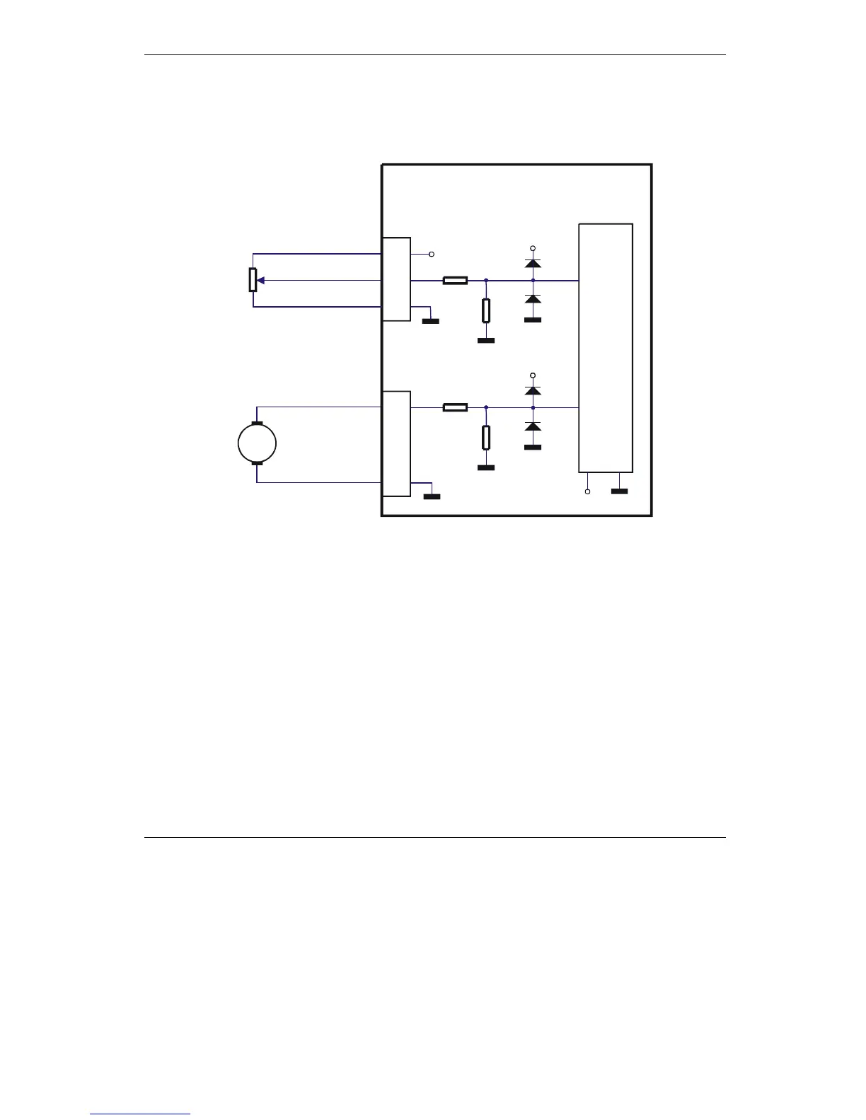
Figure 3.9. Analog inputs connection
Remark: Default input range for analog inputs is 0÷5 V. For a +/-10 V range, please contact
Technosoft.
3.2.7.2 Recommendation for wiring
a)
If the analogue signal source is single-ended, use a 2-wire shielded cable as follows: 1
st
wire connects the live signal to the drive positive input (+); 2
nd
wire connects the signal
ground to the drive negative input (-).
b) If the analogue signal source is differential and the signal source ground is isolated from
the drive GND, use a 3-wire shielded cable as follows: 1
st
wire connects the signal plus to
the drive positive input (+); 2
nd
wire connects the signal minus to the drive negative input
(-) and 3
rd
wire connects the source ground to the drive GND