© Technosoft 2007 37 IBL2403 Technical Reference
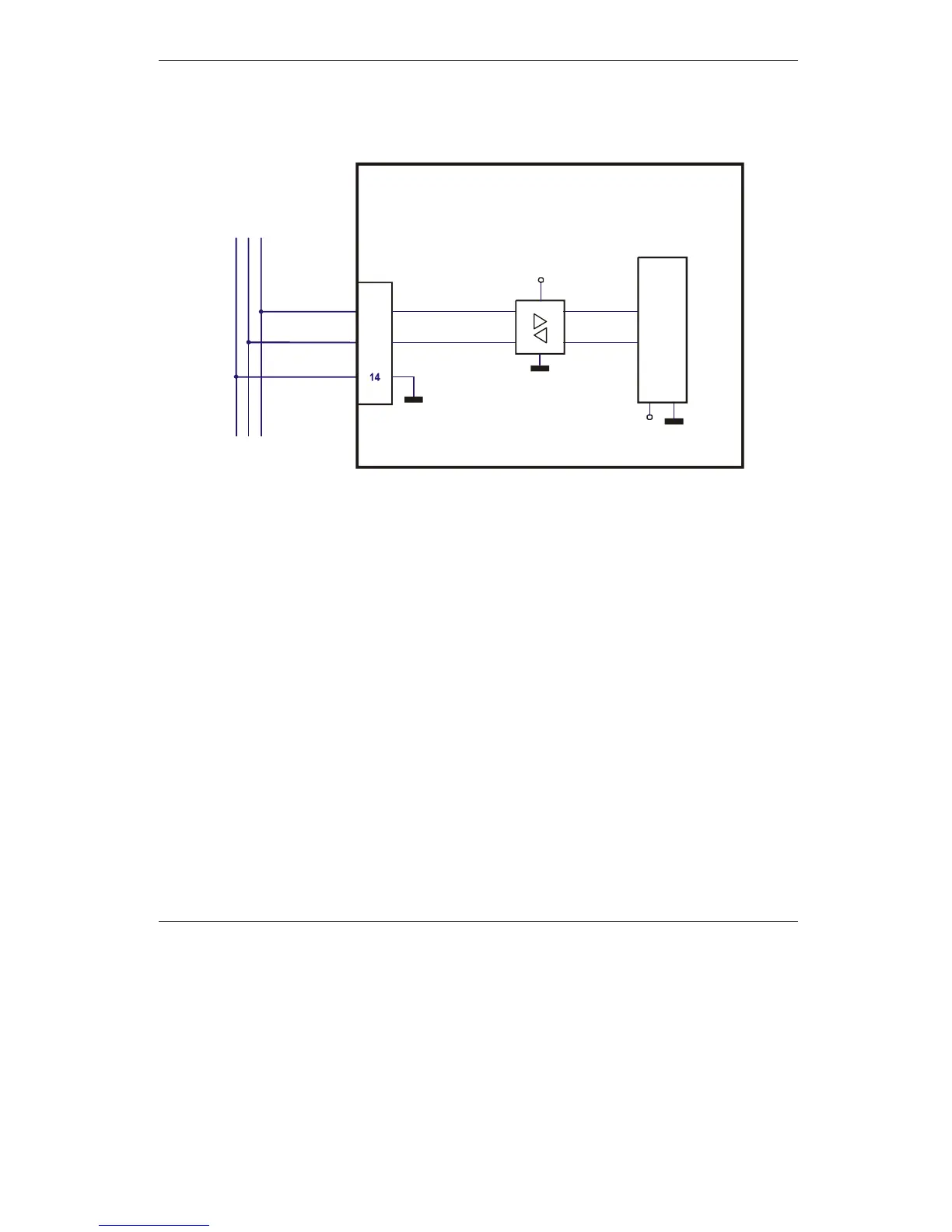
3.2.12. CAN connection (IBL2403-CAN drives)
3.2.12.1 CAN connection (IBL2403-CAN drives)
12
J1
GND
+3.3V
CAN_H
CAN_L
13
IBL2403
v1.1
CAN connection
CAN transceiver
+5V
To Previous Node
To Next Node
MotionChip
TM
Figure 3.22. CAN connection
Remarks:
1. The CAN network requires a 120-Ohm terminator. This is not included on the board.
See Figure 4.14.
2. CAN signals are not insulated from other IBL2403 circuits.
3. CAN signals (CAN_H and CAN_L pins of J1 connector) are not connected pins on the
IBL2403-RS232 drive
3.2.12.2 Recommendation for wiring
a)
Build CAN network using cables with 2-pairs of twisted wires (2 wires/pair) as follows:
one pair for CAN_H with CAN_L and the other pair for CAN_V+ with CAN_GND. The
cable impedance must be 105 ... 135 ohms (120 ohms typical) and a capacitance below
30pF/meter.
b) When total CAN bus length is below 5 meters, it is possible to use a standard phone
straight-through cable (with parallel wires)
c) Whenever possible, use daisy-chain links between the CAN nodes. Avoid using stubs. A
stub is a "T" connection, where a derivation is taken from the main bus. When stubs can’t