© Technosoft 2007 12 IBL2403 Technical Reference
2.5. Electrical Specifications
All parameters were measured under the following conditions (unless otherwise specified):
T
amb
= 25°C, power supply (V
DC
) = 24V
DC
;
Supplies start-up / shutdown sequence: -any-
;
Load current 3 A
RMS
.
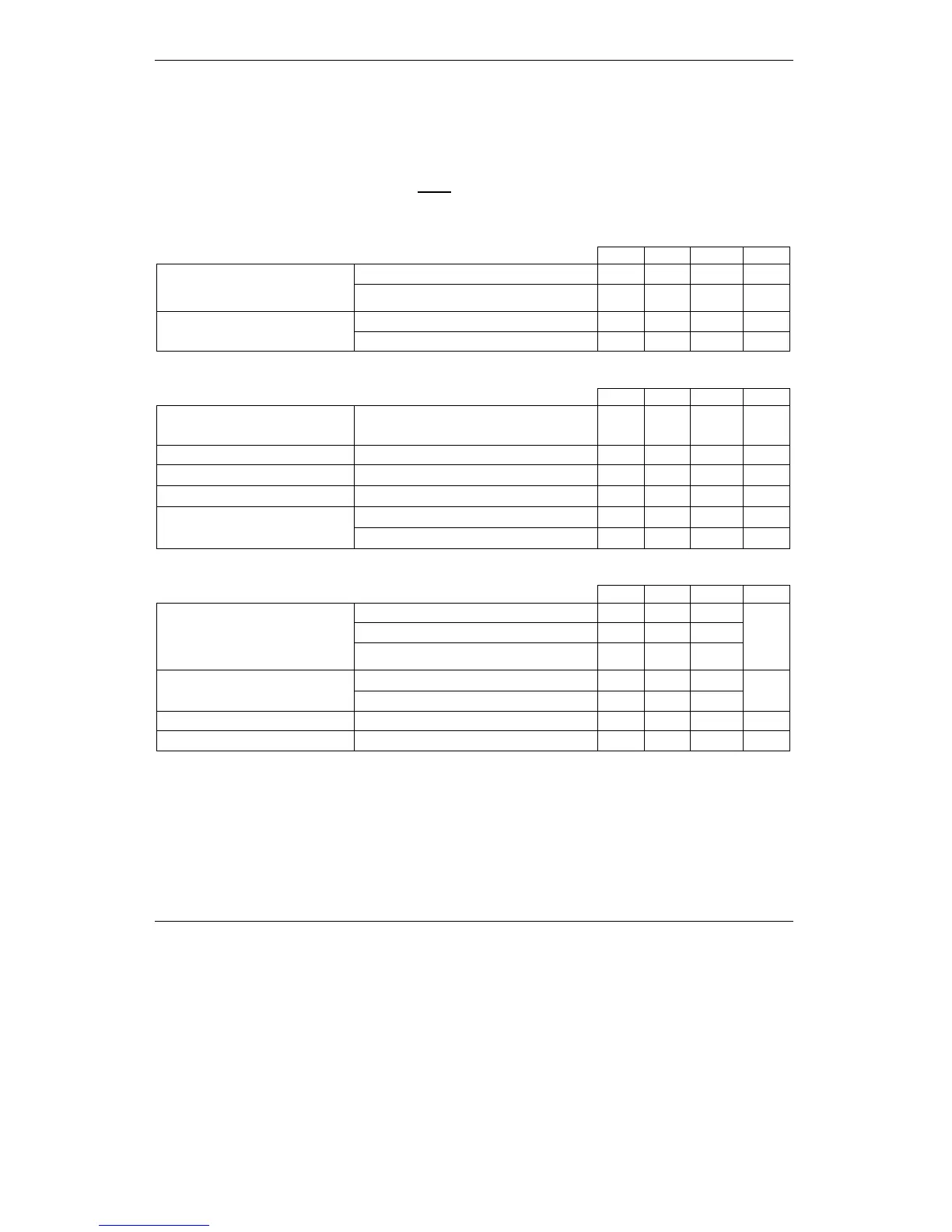
Supply Input
Measured between +V
DC
and GND.
Min. Typ. Max. Units
Nominal values 12 24 28 V
DC
Supply voltage
Absolute maximum values, continuous
†
-0.5 35 V
DC
Idle 100 250 mA Supply current
Operating -6.1 ±3 +6.1 A
Motor Outputs
All voltages referenced to GND.
Min. Typ. Max. Units
Motor output current
Continuous operation, +V
DC
= 24 V,
F
PWM
= 20 kHz
-3 +3 A
RMS
Motor output current, peak Thermal limited to <= 0.5 s -6.1 +6.1 A
On-state voltage drop
Output current = ±3 A
-900
±250
+300 mV
Off-state leakage current -1
±0.1
+1 mA
F
PWM
= 20 kHz, +V
MOT
= 12 V 50
μH
Motor inductance
F
PWM
= 20 kHz, +V
MOT
= 24 V 100
μH
Digital Inputs
All voltages referenced to GND.
Min. Typ. Max. Units
Logic “LOW” -0.5 0 0.8
Logic “HIGH” 2 5÷24 28
Input voltage
Absolute maximum, surge (duration ≤ 1S)
†
-25 +30
V
Logic “HIGH”; Internal 470 Ω pull-up to +5V
0 0 0
Input current
Logic “LOW” 8 10 13
mA
Input frequency 0 250 KHz
Minimum pulse width 5 µS