© Technosoft 2007 20 IBL2403 Technical Reference
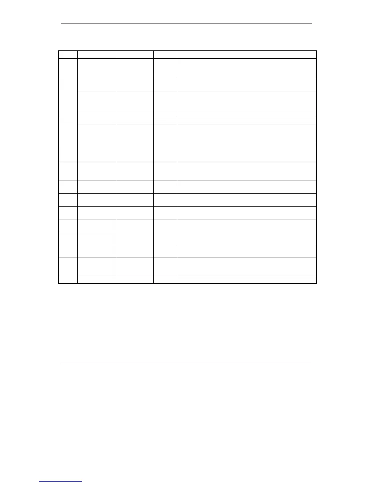
3.2.4. J2 Connector pinout
Pin Pin name TML name Type Function/Alternate function/ Comments
1
A / A+
- O
• Phase A for brushless motors
• Phase A+ for step motors
• Motor+ for DC brush motors
2
C / B+
- O
• Phase C for brushless motors
• Phase B+ for step motors
3
B / A-
- O
• Phase B for brushless motors
• Phase A- for step motors
• Motor- for DC brush motors
4
B -
- O
• Phase B- for step motors
5
GND
- -
• Ground
6
Hall 1
- I
• Hall 1 signal for digital Hall sensor
• Not-autorun. Connect all 3 Hall signals to GND in
order to disable the Autorun
7
Hall 2
-
I
• Hall 2 signal for digital Hall sensor
• Not-autorun. Connect all 3 Hall signals to GND in
order to disable the Autorun
8
Hall 3
-
I
• Hall 3 signal for digital Hall sensor
• Not-autorun. Connect all 3 Hall signals to GND in
order to disable the Autorun
9
Enc A+
- I
• Single-ended encoder A signal
• Differential encoder positive A input
10
Enc B+
- I
• Single-ended encoder B signal
• Differential encoder positive B input
11
Enc Z+
- I
• Single-ended encoder Z signal
• Differential encoder positive Z input
12
A- / LH1
-
I
• Differential encoder negative A signal
• Linear Hall 1 signal
13
B- / LH2
-
I
• Differential encoder negative B signal
• Linear Hall 2 signal
14
Z- / LH3
-
I
• Differential encoder negative Z signal
• Linear Hall 3 signal
15
Tacho
AD2 I
• Unipolar 0 V…+5 V analog input. May be used as
analog position or speed feedback (from a
tachometer)
16
+5 V
OUT
- O
• 5V logic supply (internally generated)