© Technosoft 2007 35 IBL2403 Technical Reference
In order to avoid this situation add a capacitor on the motor supply big enough to absorb the
overall energy flowing back to the supply. The capacitor must be rated to a voltage equal or
bigger than the maximum expected over-voltage and can be sized with the formula:
Drive
NOM
MAX
M
C
UU
E
C −
−
×
≥
22
2
where:
U
MAX
- is the over-voltage protection limit expressed in [V]. You can read this value in the
“Drive Info” dialogue, which can be opened from the “Drive Setup”.
C
Drive
- is the drive internal capacitance ( 220 μF)
U
NOM
- is nominal motor supply voltage expressed in [V]. You can read this value in the
“Drive Info” dialogue, which can be opened from the “Drive Setup”.
E
M
- the overall energy flowing back to the supply in Joules. In case of a rotary motor
and load,
E
M
can be computed with the formula:
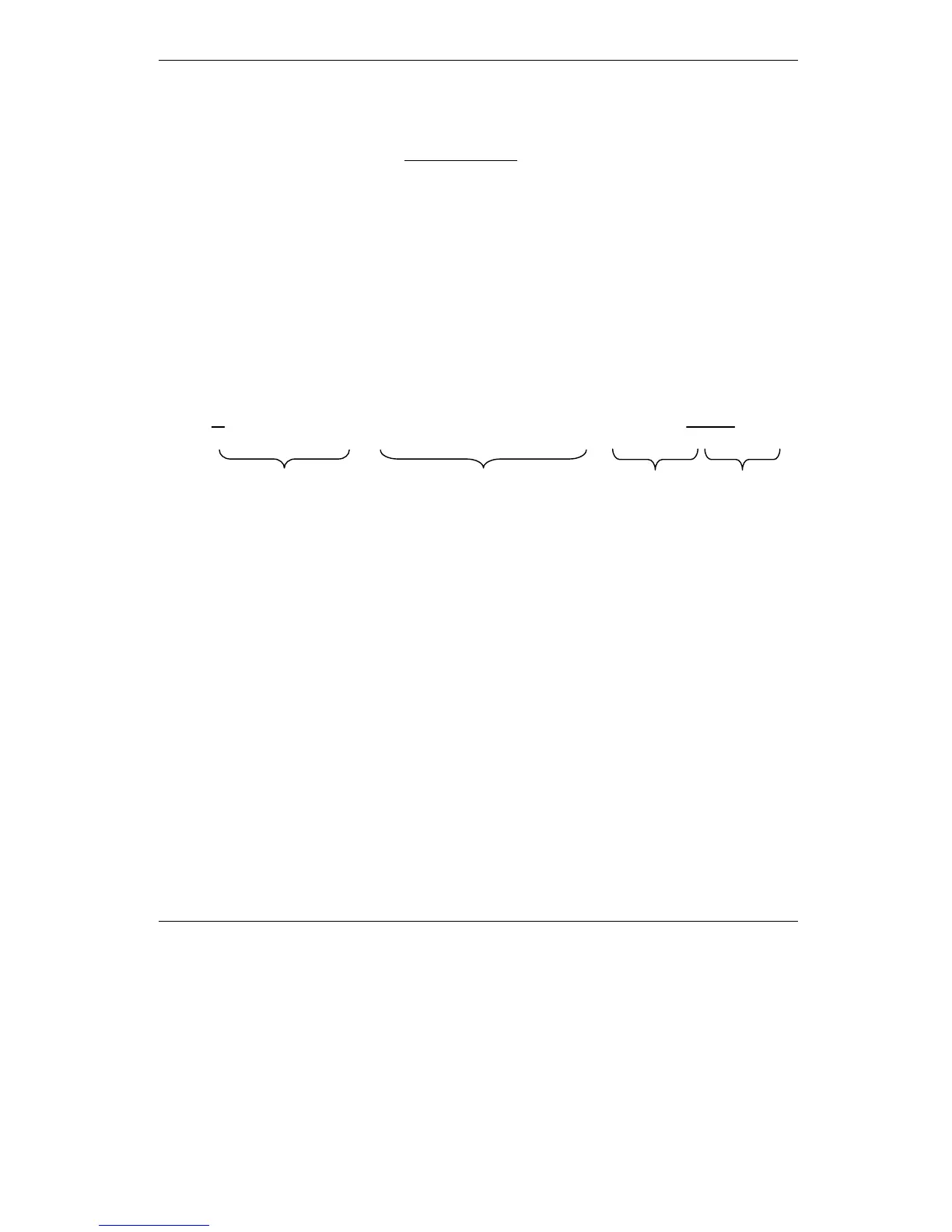
F
Md
dPh
2
M
finalinitialLMMLMM
T
2
t
tR3I)h-g(h)mm()J(J
2
1
E
ϖ
−−++ϖ+=
where:
J
M
– total rotor inertia [kgm
2
]
J
L
– total load inertia as seen at motor shaft after transmission [kgm
2
]
ϖ
M
– motor angular speed before deceleration [rad/s]
m
M
– motor mass [kg] – when motor is moving in a non-horizontal plane
m
L
– load mass [kg] – when load is moving in a non-horizontal plane
g
– gravitational acceleration i.e. 9.8 [m/s
2
]
h
initial
– initial system altitude [m]
h
final
– final system altitude [m]
I
M
– motor current during deceleration [A
RMS
/phase]
R
Ph
– motor phase resistance [Ω]
t
d
– time to decelerate [s]
T
F
– total friction torque as seen at motor shaft [Nm] – includes load and transmission
In case of a linear motor and load, the motor inertia J
M
and the load inertia J
L
will be replaced by
the motor mass and the load mass measured in [kg], the angular speed ϖ
M
will become linear
speed measured in [m/s] and the friction torque T
F
will become friction force measured in [N].
Kinetic energy Copper losses Friction losses Potential energy