TD350 Series VFD Product overview
-9-
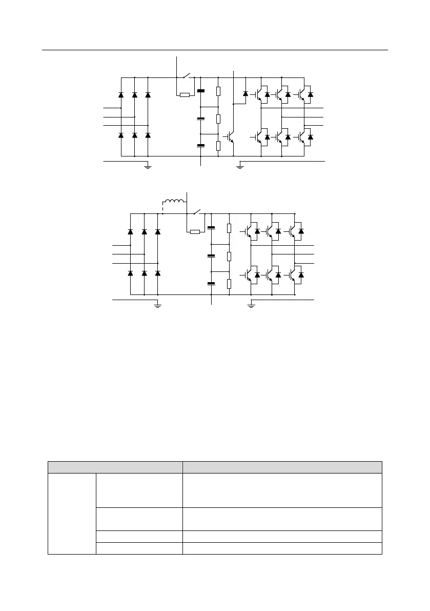
Fig 3.3 Simplified main circuit diagram (VFDs of 575V ≤18.5kW)
R
S
T
U
V
W
P1
PE PE
DC reactor
(+)
(-)
Fig 3.4 Simplified main circuit diagram (VFDs of 575V ≥22kW)
Note:
1. The VFDs of 220V (18.5–55kW), 460V (≥37kW,), and 575V (≥22kW) supports external DC
reactors and external braking units, but it is necessary to remove the copper tag between P1 and
(+) before connecting. DC reactors and external braking units are optional.
2. The VFDs of 220V (≤15kW), 460V (≤30kW,), and 575V (≤18.5kW) supports external braking
resistors which are optional.
3. The VFDs of 575V supports external DC reactors and external braking units, but it is necessary to
remove the copper tag between P1 and (+) before connecting. DC reactors and external braking
units are optional.
3.3 Product specification
AC 3PH 200V–240V Rated voltage: 220V
AC 3PH 380V–480V Rated voltage: 460V
AC 3PH 520V–600V Rated voltage: 575V
Allowable voltage
fluctuation
See Section 3.6 "Rated specifications".
50Hz or 60Hz, allowable range: 47–63Hz