TD350 Series VFD Extension cards
-313-
A.7 PG extension card function description
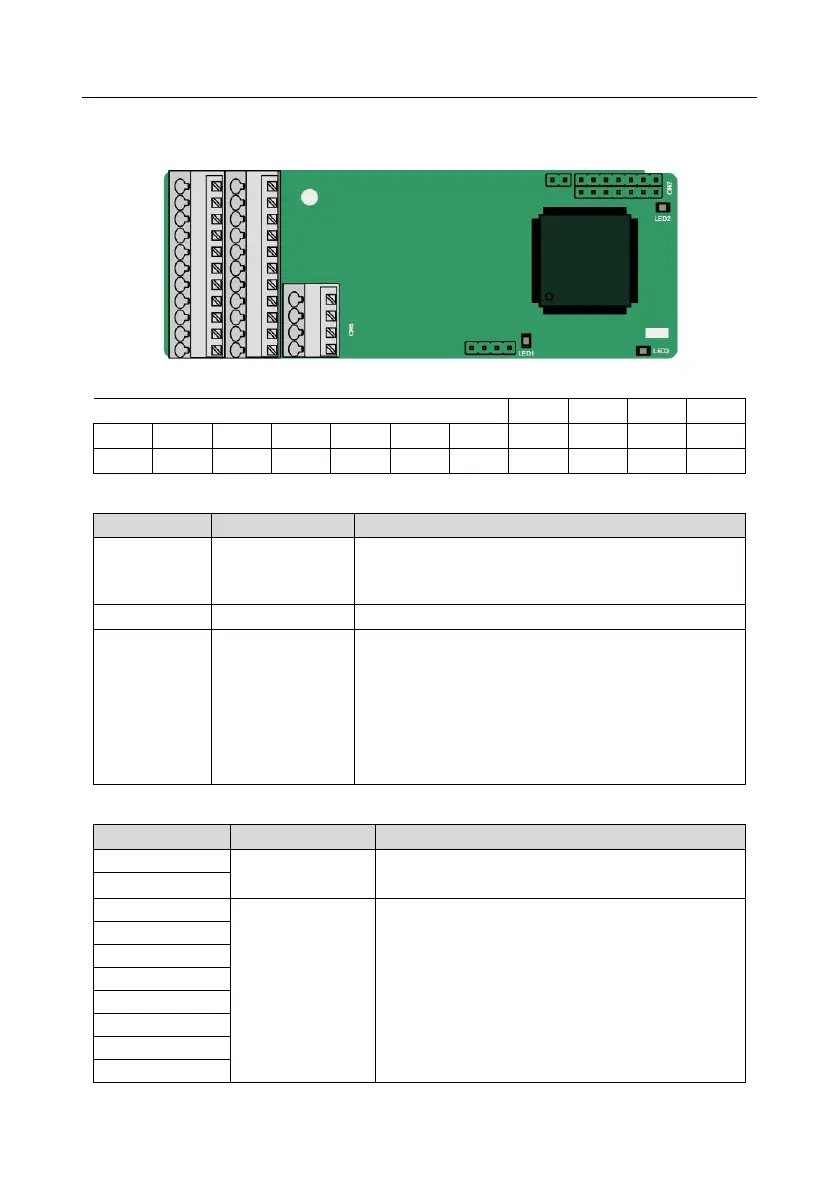
A.7.1 Sin/Cos PG card (EC-PG502)
The terminals are arranged as follows:
Definitions of indicators
Off: A1 and B1 of the encoder are disconnected.
Blinks: C1 and D1 of the encoder are disconnected.
On: The encoder signals are normal.
On: The control board feeds power to the PG card.
On: The extension card is establishing a connection
with the control board.
Blinks periodically: The extension card is properly
connected to the control board (the period is 1s, on for
0.5s, and off for the other 0.5s).
Off: The extension card is disconnected from the control
board.
EC-PG502 terminal function description
Voltage: 5 V ± 5%
Max. output current: 150 mA
1. Supporting Sin/Cos encoders (with CD signals or
without CD signals)
2. SINA/SINB/SINC/SIND 0.6–1.2Vpp; SINR 0.2–
0.85Vpp
3. Max. frequency response of A/B signals: 200 kHz
Max. frequency response of C/D signals: 1 kHz