TD350 Series VFD Installation guidelines
-33-
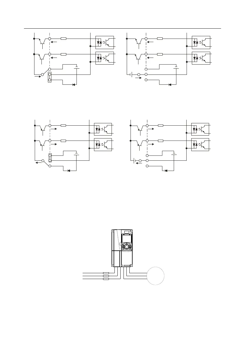
S1
S2
COM
PW
+
24V
COM
+ 24V
Internal power(NPN mode)
S1
S2
COM
PW
+ 24V
COM
+
24V
External power(NPN mode)
+ 24V
Fig 4.24 NPN mode
If input signal comes from PNP transistor, set the U-type short-contact tag based on the power used
according to the figure below.
S1
S2
COM
PW
+ 24V
COM
+ 24V
External power(PNP mode)
S1
S2
COM
PW
+ 24V
COM
+ 24V
Internal power(PNP mode)
Fig 4.25 PNP mode
4.5 Wiring protection
4.5.1 Protect the VFD and input power cable in short-circuit
Protect the VFD and input power cable during short-circuit to avoid thermal overload.
Carry out protective measures according to the following requirements.
Fig 4.26 Fuse configuration
Note: Select the fuse according to operation manual. During short-circuit, the fuse will protect input
power cables to avoid damage to the VFD; when internal short-circuit occurred to the VFD, it can
protect neighboring equipment from being damaged.