TD350 Series VFD Basic operation instructions
-35-
Chapter 5 Basic operation instructions
5.1 What this chapter contains
This chapter tells users how to use the VFD keypad and the commissioning procedures for common
functions of the VFD.
5.2 Keypad introduction
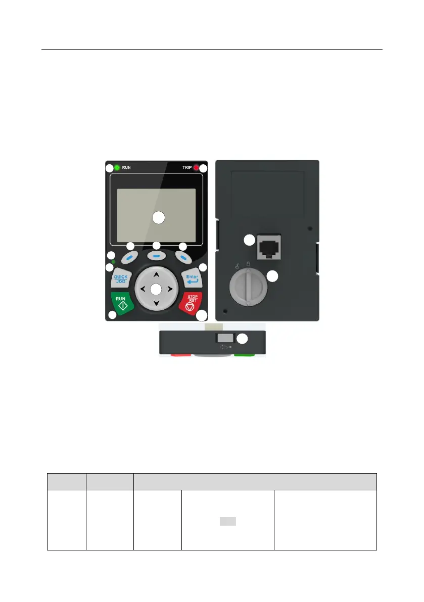
LCD keypad is included in the standard configuration of TD350 series VFD. Users can control the
VFD start/stop, read state data and set parameters via keypad.
Fig 5.1 Keypad diagram
Note:
1. LCD keypad is armed with real-time clock, which can run properly after power off when installed
with batteries. The clock battery (type: CR2032) should be purchased by the user separately;
2. LCD keypad support parameter-copy;
3. When extending the keypad cable to install the keypad, M3 screws can be used to fix the
keypad onto the door plate, or optional keypad installation bracket can be used. If you need
install the keypad on another position rather than on the VFD, use a keypad extension cable
with a standard RJ45 crystal head.
Running indicator;
LED off – the VFD is stopped;
LED blinking – the VFD is in
parameter autotune
LED on – the VFD is running