TD350 Series VFD Optional peripheral accessories
-358-
D.8 Brake system
D.8.1 Brake component selection
When a VFD driving a high-inertia load decelerates or needs to decelerate abruptly, the motor runs in
the power generation state and transmits the load-carrying energy to the DC circuit of the VFD,
causing the bus voltage of the VFD to rise. If the bus voltage exceeds a specific value, the VFD
reports an overvoltage fault. To prevent this from happening, you need to configure brake
components.
The design, installation, commissioning, and operation of the device must be
performed by trained and qualified professionals.
Follow all the "Warning" instructions during the operation. Otherwise, major
physical injuries or property loss may be caused.
Only qualified electricians are allowed to perform the wiring. Otherwise,
damage to the VFD or brake components may be caused.
Read the brake resistor or unit instructions carefully before connecting them
to the VFD.
Connect brake resistors only to the terminals PB and (+), and brake units
only to the terminals (+) and (-). Do not connect them to other terminals.
Otherwise, damage to the brake circuit and VFD and fire may be caused.
Connect the brake components to the VFD according to the wiring diagram. If
the wiring is not properly performed, damage to the VFD or other devices
may be caused.
TD350 series VFDs below 220V (≤15kW), 460V (HD (CT)≤30kW) need internal brake units and the
VFDs 220V (≥18.5kW), 460V (HD (CT)≥37kW) need external brake units. Select the resistance and
power of brake resistors according to actual utilization.
The VFDs of 220V (≤15kW), 460V (HD (CT)≤30kW) are configured with brake units but brake units
are optional for the VFDs of 220V (≥18.5kW), 460V (HD (CT)≥37kW). Select brake resistors
according to actual operation.
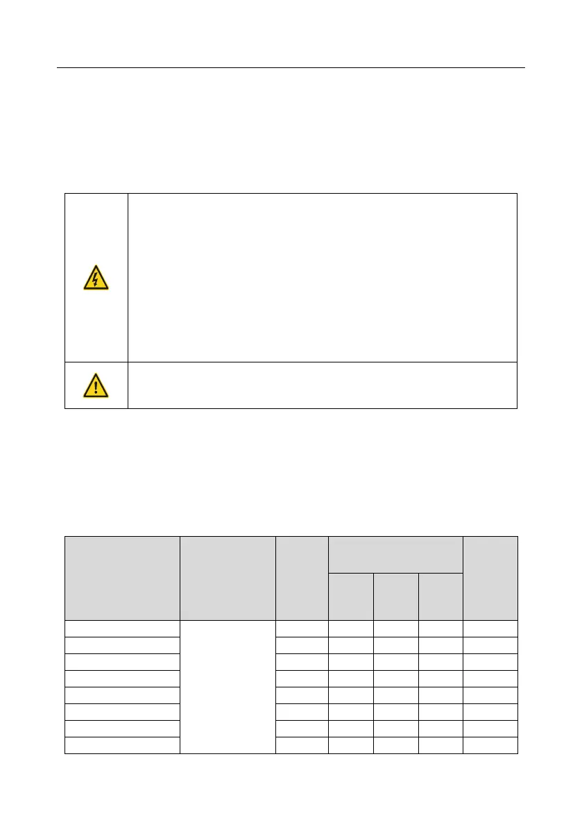
Brake
resistor at
100% of
braking
torque (Ω)
Consumed power of brake
resistor
Min.
allowable
braking
resistance
(Ω)