TD350 Series VFD Optional peripheral accessories
-355-
Note:
The rated input voltage drop of input reactors is 2%±15%.
The power factor on the input side of the VFD is higher than 90% after a DC reactor is configured.
The rated output voltage drop of output reactors is 1%±15%.
The preceding table describes external accessories. You need to specify the ones you choose
when purchasing accessories.
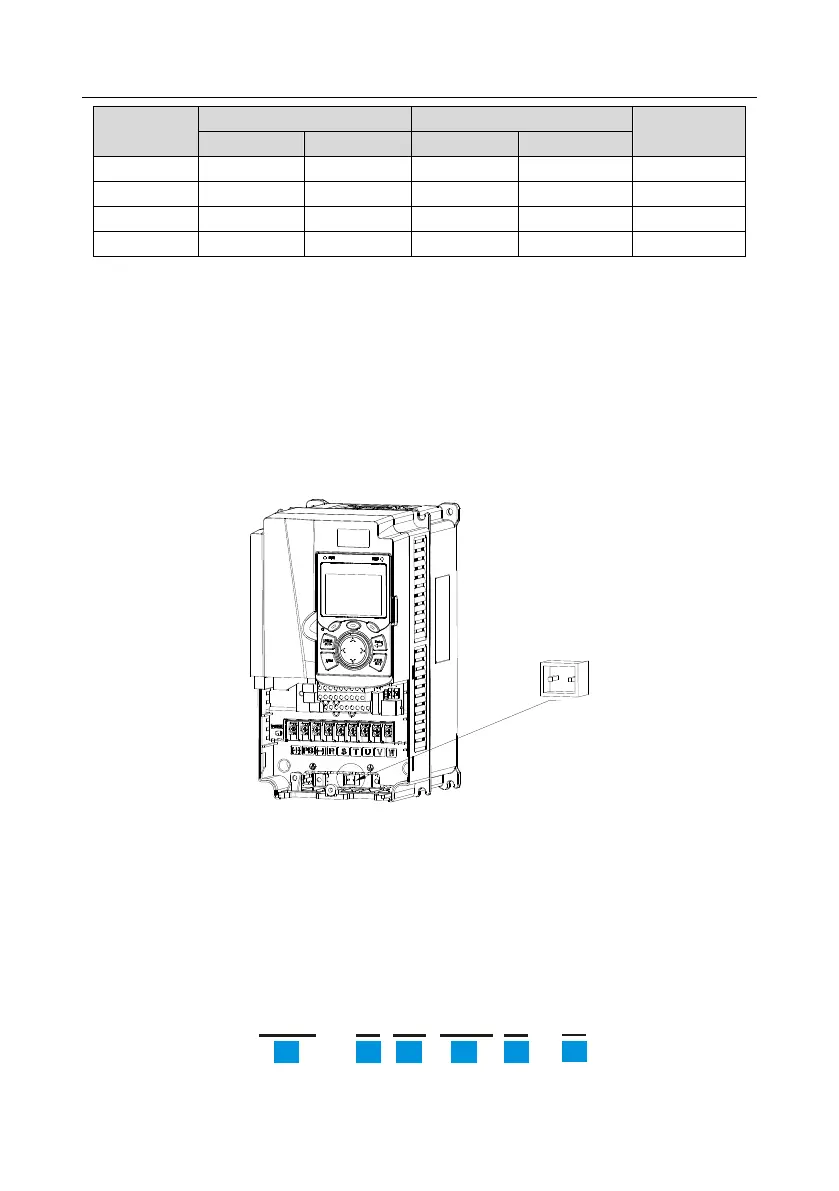
D.7 Filters
TD350 series VFDs are configured with built-in C3 filters which can be connected by J10.
Note: Do not connect C3 filters in IT power systems.
Interference filters on the input side can reduce the interference of VFDs (when used) on the
surrounding devices.
Noise filters on the output side can decrease the radio noise caused by the cables between VFDs and
motors and the leakage current of conducting wires.
TECHTOP provides some of the filters for users to choose.
D.7.1 Filter model description