TD350 Series VFD Installation guidelines
-32-
Duty ratio: 30%–70%;
Supports quadrature encoder input; equipped with speed-measurement function
Safe torque off (STO) redundant input, connect to external NC
contact, STO acts when the contact opens, and the VFD stops
output;
Safety input signal wires use shielded wire whose length is within
25m;
H1 and H2 terminals are short connected to +24V by default; it is
required to remove the short-contact tag on the terminal before
using STO function.
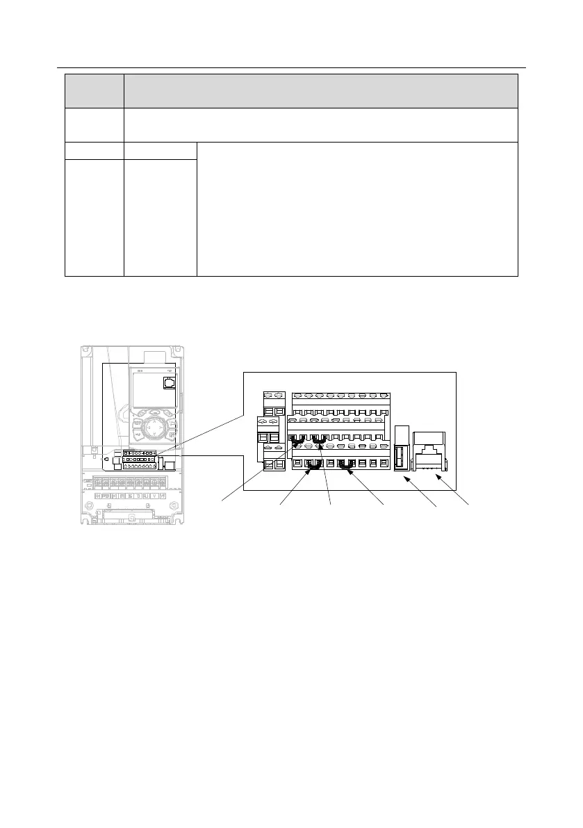
4.4.2 Input/output signal connection diagram
Set NPN /PNP mode and internal/external power via U-type short-contact tag. NPN internal mode is
adopted by default.
U-type short-
contact tag of H2
and +24V
U-type short-contact
tag of COM and
+CME
U-type short-
contact tag of
+24V and PW
U-type short-
contact tag of H1
and +24V
+24V
485++24V CME 485-485GCOMCOMPE H2
R01CR02C
H1 +24V
R01BR02B
PW COM HDO Y1 AO1 GND
S1 S2 S3 S4 HDIA HDIB AI1 AI2 +10V
R01AR02A
USB port
Keypad port
Fig 4.23 Position of U-type short-contact tag
Note: As shown in Fig 4.23, the USB port can be used to upgrade the software, and the keypad port
can be used to connect an external keypad. The external keypad cannot be used when the keypad of
the VFD is used.
If input signal comes from NPN transistors, set the U-type short-contact tag between +24V and PW
based on the power used according to the figure below.