TD350 Series VFD Function parameter list
-152-
Detailed parameter description
Output voltage
Output
frequency
Cut-off
boost
b
f
f
v
v
Setting range of P04.01: 0.0%: (automatic) 0.1%–
10.0%
Setting range of P04.02: 0.0%–50.0%
V/F frequency
point 1 of motor 1
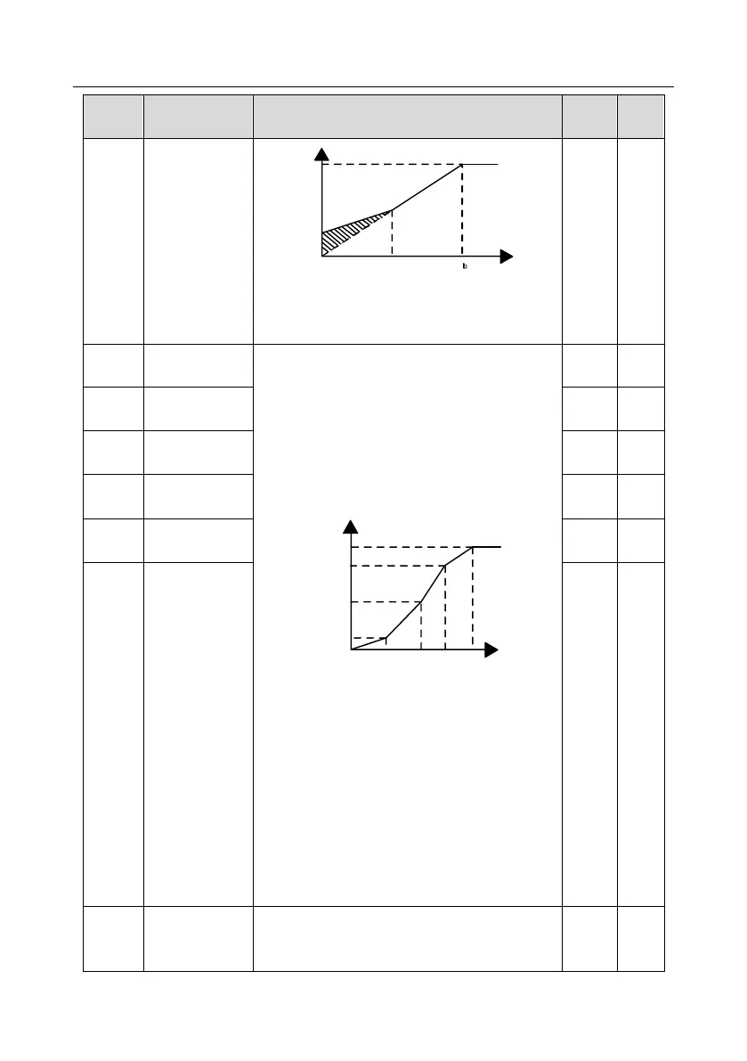
When P04.00 =1 (multi-point V/F curve), users can
set V/F curve via P04.03–P04.08.
V/F curve is usually set according to the
characteristics of motor load.
Note: V1<V2<V3, f1<f2<f3. If low-frequency
voltage is set too high, motor overheat or
burnt-down may occur, and overcurrent stall or
overcurrent protection may occur to the VFD.
Output voltage
Output
frequency(Hz)
V1
V2
V3
f1 f2 f3
100.0%
b
f
b
V
Setting range of P04.03: 0.00Hz–P04.05
Setting range of P04.04: 0.0%–110.0% (rated
voltage of motor 1)
Setting range of P04.05: P04.03–P04.07
Setting range of P04.06: 0.0%–110.0% (rated
voltage of motor 1)
Setting range of P04.07: P04.05–P02.02 (rated
frequency of asynchronous motor 1) or P04.05–
P02.16 (rated frequency of synchronous motor 1)
Setting range of P04.08: 0.0%–110.0% (rated
voltage of motor 1)
V/F voltage point
1 of motor 1
V/F frequency
point 2 of motor 1
V/F voltage point
2 of motor 1
V/F frequency
point 3 of motor 1
V/F voltage point
3 of motor 1
V/F slip
compensation
gain of motor 1
This parameter is used to compensate for the motor
rotating speed change caused by load change in
the SVPWM mode, and thus improve the rigidity of