TD350 Series VFD Extension cards
-311-
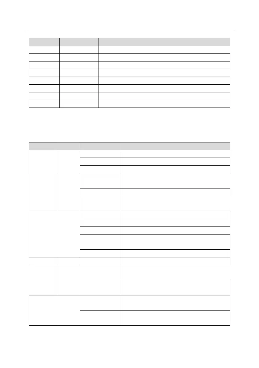
Standard RJ45 interface functions
State indicators
The EtherNet/IP communication card provides four LED indicators and four net port indicators to
indicate its states.
The card is shaking hands with the VFD.
The card and VFD communicate normally.
The card and VFD communicate improperly.
The communication between the card and PLC is
online and data interchange is allowed.
IP address conflict between the card and PLC.
The communication between the card and PLC is
offline.
Failed to set up I/O between the card and PLC.
Incorrect PLC configuration.
The card failed to send data to the PLC.
The connection between the card and PLC timed
out.
Link indicator, indicating successful Ethernet
connection.
Link indicator, indicating Ethernet connection not
established.
ACK indicator, indicating data interchange being
performed.
ACK indicator, indicating data interchange not be
performed.