TD350 Series VFD Installation guidelines
-29-
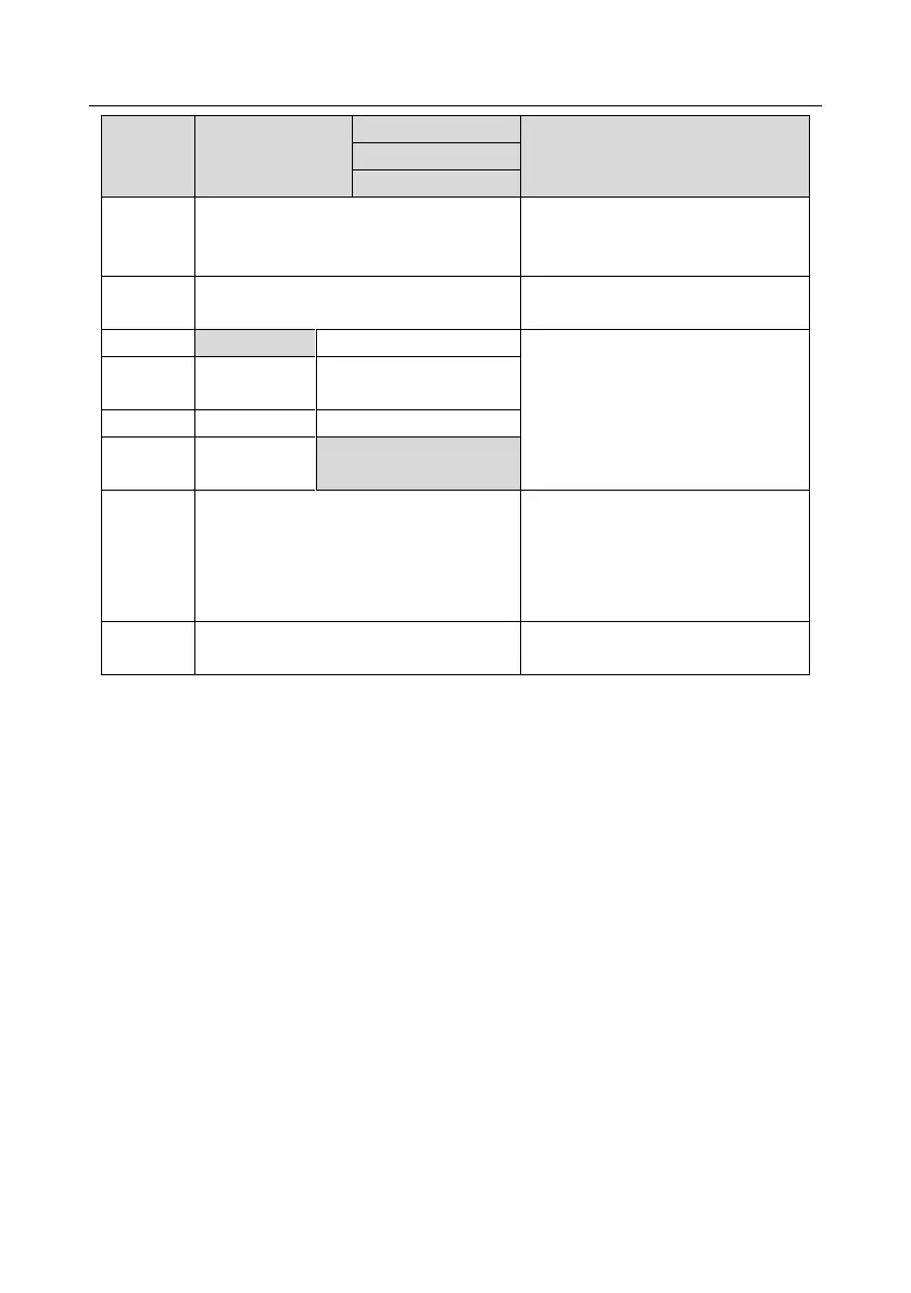
220V≤15kW
460V ≤30kW
575 ≤18.5kW
Power input of the main circuit
3-phase AC input terminals which are
generally connected with the power
supply.
3-phase AC output terminals which are
generally connected with the motor.
P1 and (+) are connected with the
terminals of DC reactor.
(+) and (-) are connected with the
terminals of braking unit.
PB and (+) are connected with the
terminals of braking resistor.
DC reactor terminal 2,
braking unit terminal 1
460V: the grounding resistor is less than
10Ohm
Protective grounding terminals, every
machine is provided 2 PE terminals as
the standard configuration. These
terminals should be grounded with
proper techniques.
Control power supply terminal
Optional parts (external 220V control
power supply)
Note:
1. VFDs of 575V 0.75–18.5kW do not carry P1, A1, or A2.
2. Do not use asymmetrical motor cable. If there is a symmetrical grounding conductor in the motor
cable besides the conductive shielded layer, ground the grounding conductor on the VFD end
and motor end.
3. Brake resistor, brake unit and DC reactor are optional parts.
4. Route the motor cable, input power cable and control cables separately.
5. If the terminal description is "/", the machine does not provide the terminal as the external
terminal.
4.3.3 Wiring process of the main circuit terminals
1. Connect the grounding line of the input power cable to the grounding terminal (PE) of the VFD,
and connect the 3PH input cable to R, S and T terminals and tighten up.
2. Connect the grounding line of the motor cable to the grounding terminal of the VFD, and connect
3PH motor cable to U, V and W terminals and tighten up.
3. Connect the brake resistor which carries cables to the designated position.
4. Fix all the cables outside the VFD mechanically if allowed.