EasyManua.ls Logo

TECHTOP TD350 - Page 348

TECHTOP TD350
371 pages
Print Icon
To Next Page IconTo Next Page
To Previous Page IconTo Previous Page
Loading...
TD350 Series VFD Dimension drawings
-343-
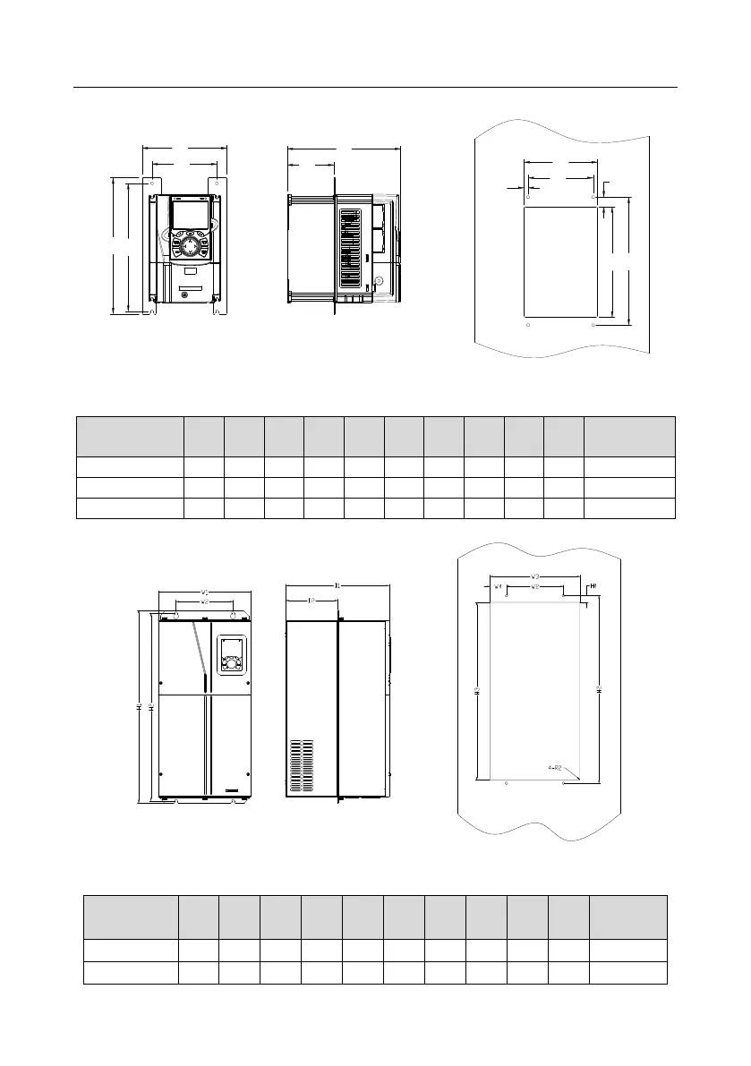
C.5.2 Flange installation dimensions
H1 H2
W1
W2
D1
D2
W3
W2
W4
H4
H2H3
Fig C.15 Flange installation diagram of VFDs of 575V 0.7518.5kW
Table C.8 Flange installation dimensions of VFDs of 575V 0.7518.5kW (unit: mm)
VFD
specification
W1
W2
W3
W4
H1
H2
H3
H4
D1
D2
Installation
hole
0.75kW2.2kW
170.2
131
150
9.5
292
276
260
10
192
78
Ø 5
4kW-7.5kW
191.2
151
174
11.5
370
351
324
15
219
113
Ø 6
11kW18.5kW
250.2
210
234
12
375
356
334
10
217
108
Ø 6
Fig C.16 Flange installation diagram of VFDs of 575V 22110kW
Table C.9 Flange installation dimensions of 575V 22110kW (unit: mm)
VFD
specification
W1
W2
W3
W4
H1
H2
H3
H4
D1
D2
Installation
hole
22kW37kW
270
130
261
65.5
555
540
516
17
325
167
Ø 7
45kW110kW
325
200
317
58.5
680
661
626
23
363
182
Ø 9.5

Table of Contents

Other manuals for TECHTOP TD350

Related product manuals