TD350 Series VFD Optional peripheral accessories
-361-
D.8.2 Brake resistor cable selection
Brake resistor cables need to be shielded cables.
D.8.3 Brake resistor installation
All resistors need to be installed in places with good cooling conditions.
The materials near the brake resistor or brake unit must be non-flammable. The
surface temperature of the resistor is high. Air flowing from the resistor is of
hundreds of degrees Celsius. Prevent any materials from coming into contact
with the resistor.
Installation of brake resistors
The VFDs of 220V (≤15kW), 460V (HD (CT)≤30kW), and 575V (≤18.5kW) only
need external brake resistors.
PB and (+) are the wiring terminals of the brake resistors.
VFD
PB
External brake resistor
+
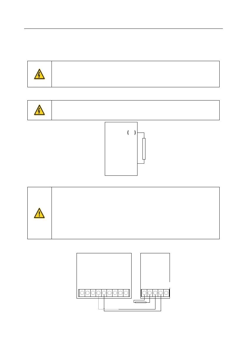
Installation of brake units
The VFDs of 220V (≥18.5kW) need external braking units.
The VFDs of 460V (≥37kW) need external braking units.
The VFDs of 575V (≥22kW) need external braking units.
(+), (-) are the wiring terminals of the braking units.
The wiring length between the (+), (-) terminals of the VFD and the (+), (-)
terminals of the braking units should be no more than 5m, and the distributing
length among BR1 and BR2 and the braking resistor terminals should be no
more than 10m.
The following figure shows the connection of one VFD to a dynamic brake unit.
+ + + + +++
External brake
resistor RB
(+)
DC+
(-)
DC-
BR1 BR2 PE(-)(+)
++ + + + ++
VFD
DBU
brake unit