TD350 Series VFD Basic operation instructions
-40-
The stop display parameter list is defined by the user, and each state variable function code can be
added to the stop display parameter list as needed. The state variable which has been added to the
stop display parameter list can also be deleted or shifted.
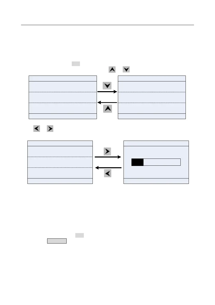
5.3.2 Running parameter display state
After receiving valid running command, the VFD will enter running state, and the keypad displays
running state parameter with RUN indicator on the keypad turning on. Under running state, multiple
kinds of state parameters can be displayed. Press or to shift up or down.
01: TD350
16:02:35
OutpFreq
P17.01 Hz
50.00
Set Freq
P17.00 Hz
50.00
540.0
DC Bus Volt
P17.11 V
01: TD350
16:02:35
Set Freq
P17.00 Hz
50.00
DC Bus Volt
P17.11 V
540.0
378
Outp Volt
P17.03 V
Fwd
Local Run
Fwd
Local
Run
AboutMonitor
Menu
AboutMonitor
Menu
Fig 5.5 Running parameter display state
Press or to switch between different display styles, including list display style and progress
bar display style.
01: TD350
16:02:35
Fwd
Local Ready
DC Bus Volt
Return
Homepage
0.0 2000.0
01: TD350
16:02:35
Fwd
Local Ready
DC Bus Volt
P17.11 V
540.00
DigiInputTrmState
P17.12
0x0000
0x0000
AboutMonitor
Menu
DigiOutpTrmState
P17.13
540.00
V
Fig 5.6 Running parameter display state
Under running state, multiple kinds of state parameters can be displayed. The running display
parameter list is defined by the user, and each state variable function code can be added to the
running display parameter list as needed. The state variable which has been added to the running
display parameter list can also be deleted or shifted.
5.3.3 Fault alarm display state
The VFD enters fault alarm display state once fault signal is detected, and the keypad displays fault
code and fault information with TRIP indicator on the keypad turning on. Fault reset operation can be
carried out via STOP/RST key, control terminal or communication command.
The fault code will be kept displaying until fault is removed.